You are here
[Help]: Element length increase in bending process without strain increase
Mon, 2015-04-27 02:12 - tuanpham
hello everybody,
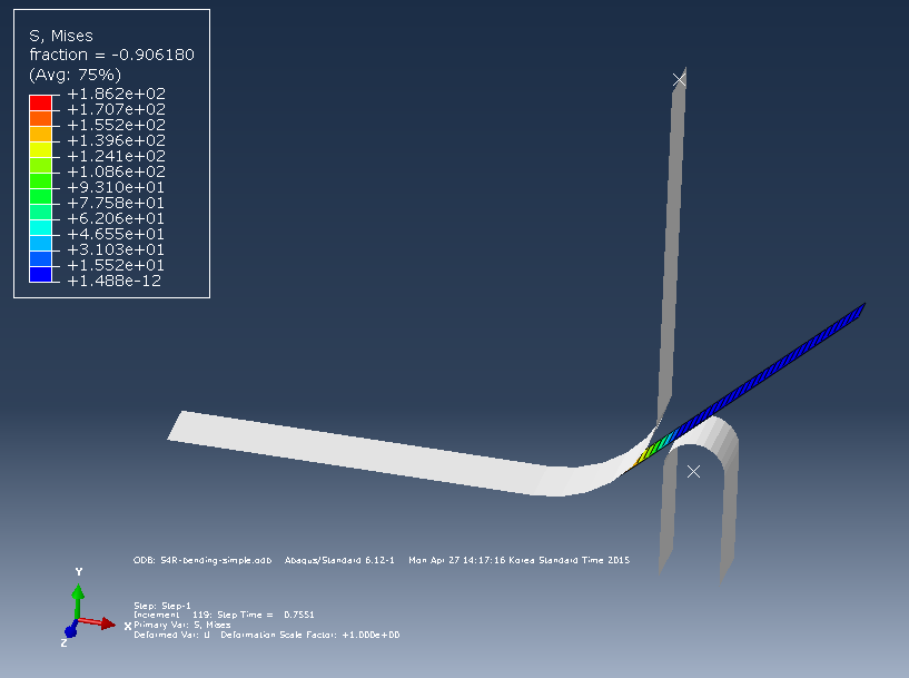
I am a feshmen in ABAQUS simulation. I want to simulate a basic problem: sheet metal bending process where the die is fixed, the punch move up and bend the sheet with the die shape. Please finding in Fig 1 for more detailed information.
My problem is the elements, which are lying after bending area, have been increased it's length. However, the stress and strain of this elements are almost equal to zero.
I think it's my simulation mistake and I am confuesing about this problem. I have found in internet but I don't understand why it work like that and how to correct it. I hope someone can help me explain this mistake and solve this problem.
Thanks.
| Attachment | Size |
|---|---|
| 24.9 KB | |
| 21.78 KB | |
| 96.37 KB |
Forums:
First, can you confirm that
First, can you confirm that you're running with NLGEOM=on? Are you using Standard or Explicit? Do the elements look like they're twice as long as they were?
In your field outputs, include "LE" which is the strain components. If those elements have 0 (or nearly 0) strain as measured with LE, then you're fine.
Thank for your advice
Dear Marcus Rademacher,
Thanks to your advice, I found my mistake and corrected it. The problem is I set NLGEOM=off in abaqus Standard. When I run with NLGEOM=on, It work perfectly.
Again, thank you for your useful help.
Sincerely yours,
Glad it was fixed. The use of
Glad it was fixed. The use of the NLGEOM option has an important theoretical background, so you might want to ask your professor about that. One key part of that is the different strain measures used in linear vs. nonlinear analysis. What you saw is where if you rotate an element without stressing or straining it you will actually get nonzero strain output if you use the linear strain measure. If you use a nonlinear strain measure it will correctly output 0.
Dear Marcus Rademacher and
Dear Marcus Rademacher and everyone who are reading,
Thank you very much for your discussion. And I am sorry to disturb you one more time.
I want to simulate a bending problem, where the die was fixed, the clamp rotate around the axis which is normal the picture, and the clamp is tie with a bar in local area. For detail, please finding in figure 1.
My problem is after bending, the clamp (discrete rigid body) have changed the shape. I expect the clamp shape no change during bending process but It changed. And I don't know how to correct it although I have found many times in internet as well as read abaqus documentation. I hope you can show me the way to correct it.
Thank you very much for your attention.
Sincerely your.
Your images didn't show up,
Your images didn't show up, and I didn't follow the description without them. A rigid part should not deform, but it can translate and rotate. Post a couple pictures of the issue and I'll take a look.
Dear Mr. Marcus Rademacher,
Dear Mr. Marcus Rademacher,
I can't upload image to this post. Please go to the link I have attached to find figures.
thanks you so much.
initial state
http://s803.photobucket.com/user/tuanpham0101/media/1.png.html?sort=3&o=1
after bending
http://s803.photobucket.com/user/tuanpham0101/media/2.png.html?sort=3&o=0
That rigid clamp does look
That rigid clamp does look like it deformed. I can't say why, other than it must not be correctly defined as rigid. If you plot stresses, does it show stress values on the rigid part?
Dear Mr. Marcus,
Dear Mr. Marcus,
I have created the clamp as a discrete rigid body which element type is R2D2. And obviously, It doesn't have stress value. When I check the degree 6-UR3 (rotation in z axis) of the nodes in the clamp, only reference node rotated with the value that I have set. The others nodes keep it's UR3 rotation by zero. So, I think this problem occur only because of the visualization error. But I don't know how to correction the visualization in abaqus. (I have set the deformation scale factor by 1, but it's no change the display results). Do you have any idea about visualization in ABAQUS?
Thank you for your attention.
The whole part is rotated
The whole part is rotated about the RP? That would be consistent with how rigid parts work. Maybe I just misinterpreted the first set of images. It's looking like this is acting as it should.