You are here
Basic dimensioning
Dear all,
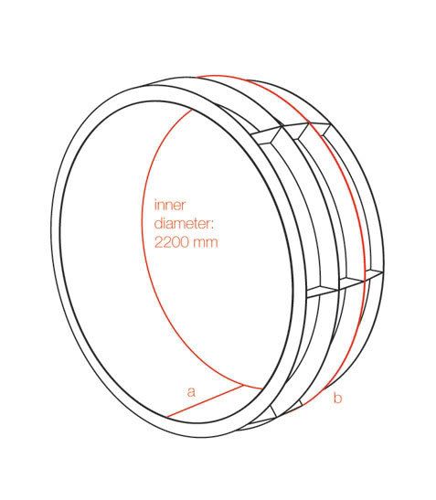
Above is a proposal for a human wheel I would like to make, the inner cylinder would be perforated with holes smaller than the smallest finger without making it non-transparent. The difference with a hamster wheel is that it wouldn’t be stationary and is able to take ( large ) bends. The ribs seem rounded, but that’s only an optical illusion. The intention of the wheel is to give an alternative to the walking paths ( paved green space to keep your shoes clean ) in parks, a new experience with more freedom.
“I am sure we have all heard of physics groups and classes in school building trebuchets or catapults. They are planning on storming a castle about as much as we are planning on giving extra large hamsters exercise.”
There will be a first estimation of the thickness of the materials (the rings shouldn't be able to amputate a hand, but shouldn't destroy too much grass either), the amount of crossbars and the diameter of the outer rings (wider than the palm of a big hand) using the Cosmos-software. The structure as drawn above would weigh ±80kg in TIG welded aluminium AW-5083 with anti-slip paint, maybe fibreboard is an option too.
But I was wondering how to define the:
- width of the cylinder a
- diameter of the two rings in the middle b
to make sure:
1) the wheel is not too heavy to make it start/stop rolling
2) it is not too difficult to make the wheel lean to one side
3) the wheel is unlikely to fall
( 4)the bends it can take are not too large )
1)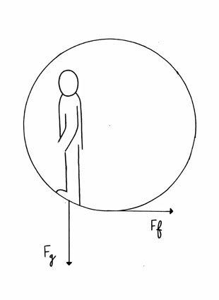
The two forces that I think decide whether the wheel is going to roll or not - rolling resistance and gravity on the person - seem to work in different directions?
2)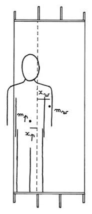
The wheel will lean to one side when the combined centre of mass of the wheel and the person in it is not positioned above the resting surface.
(mw.xw - mp.xp) / (mw + mp) = 0
This can be reduced to a function of a and b.
3)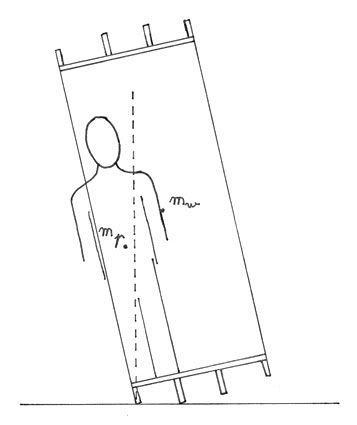
The wheel will not fall when the combined centre of mass is positioned above the resting surface.
But what is the influence of inertia - as a result of the leaning movement - on the position of the combined centre of mass?
All of these could result in a graph with a and b as axes from which I could deduct their ideal value.
Parks are not perfectly flat and there might be wind, so I will have to build in safety margins.
This product designer is thanking you in advance!
Worst case scenario
I’ll also have to think about the worst case scenario: people could deliberately tip over the wheel,
there might be a storm (putting the wheel on its side helps)
and the angular momentum makes that the braking distance is relatively long.