
We present below some of the works obtained in a joint project in the recent year on the modelling of fracture in concrete from direct experimental imaging and combined 3D X-ray micro-tomography, in-situ testing, and 3D phase field simulations. Among the different results, we highlight:
· The first use of the phase field method to simulate fracture in concrete from direct imaging of their microstructure obtained by micro-CT.
https://hal-upec-upem.archives-ouvertes.fr/hal-01140963/file/%5B54%20PP%5D.pdf
· The first direct comparisons, to our best knowledge, of 3D fracture networks in concrete between experiments and phase field simulations
· The use of 3D image correlation to provide boundary conditions for the simulation in small samples extracted from a large 3D image.
· An inverse approach to identify microscale damage parameters
https://hal-upec-upem.archives-ouvertes.fr/hal-01331213/document
· A simple interface damage model within the context of phase field to take into account particle debounding interacting with matrix cracks.
https://hal-upec-upem.archives-ouvertes.fr/hal-01213943/file/%5B56%5DPP.pdf
· Comparisons between experimental cracks and phase field simulations in drilled plaster samples loaded in compression.
https://hal-upec-upem.archives-ouvertes.fr/hal-01258035/file/%5B59%5D%20PP.pdf
· The detection and extraction of microcracks from micro-CT images of the heterogenous and porous microstructure of concrete under in situ loading using digital volume correlation
https://onlinelibrary.wiley.com/doi/abs/10.1111/str.12276
(a) (b)
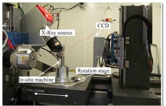
Fig. 1 (a) Global view of the in situ compression test combined with XR-μCT at Laboratoire Navier; (b) Sample of lightweight concrete.
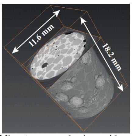
Fig. 2: (a) Full CT image of a lightweight concrete; (b) cut within the sample.
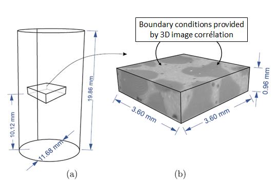
Fig. 3:(a) location of the sub-volume in the sample; (b)XR-μCT images of the sub-volume.
(a) (b)
Fig. 4: Experimental crack network at fully broken state of plaster sample embedding PE beads (b)simulated crack with phase field at an early stage of propagation.
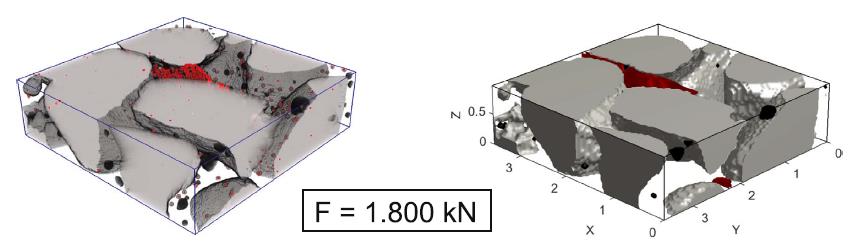
Experimental Simulation
Fig. 5: Comparison between experimental crack obtained from microtomography and from phase field method of the lightweight concrete sample in a sub-volume.
Fig. 6: Compression test on a microtomography image-based model of EPS lightweight concrete taking into account interfacial damage.
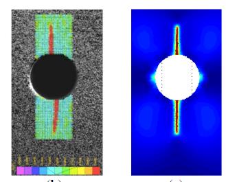
(a) (b)
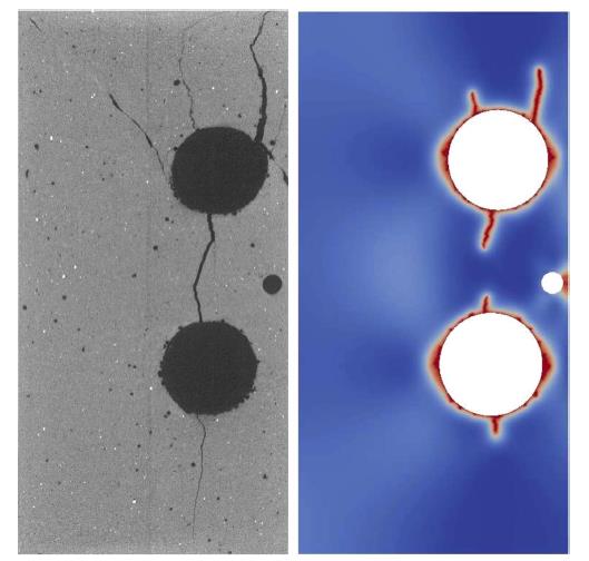
Fig. 7: Crack path evolution near the cylindrical hole (D = 5mm); (a) strain maps obtained with digital image correlation (b) 2D simulation (plane strain), (c) Evolution of the crack length with respect to the resultant stress on the upper boundary, comparison between models and experimental data: (top crack)
Acknowledgements: This work has benefited from a French government grant managed by ANR within the frame of the national program Investments for the Future ANR-11-LABX-022-01.