Hi,
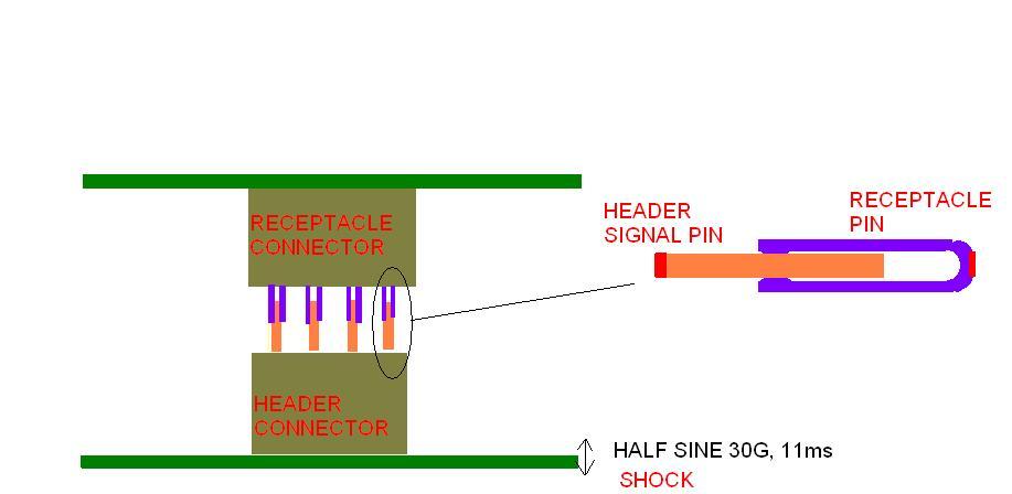
I'm going to run a shock analysis on FEA software on two mated electronic connectors sitting on PCB. Shock test has shown that the half sine shock is causing discontinuity in signal between the mated connectors. But I'm not sure how I should apply the boundary condition with half sine acceleration shock at the pin level (both ends of mated pins). If I apply acceleration in the mating direction on the signal pin, it will keep going forward without stopping even when the acceleration is zero, down from the peak 30G, and hit the recept pin. Should I specify displacement instead of acceleration with the signal pin so that signal pin can return to original position after shock & look at the response of the assembly?
I've attached the picture of the connectors here.
I've never performed shock test/analysis before so I'm not confident about the boundary conditions to apply. Please advise.
Thanks
| Attachment | Size |
|---|---|
| SHOCK.JPG | 28.88 KB |