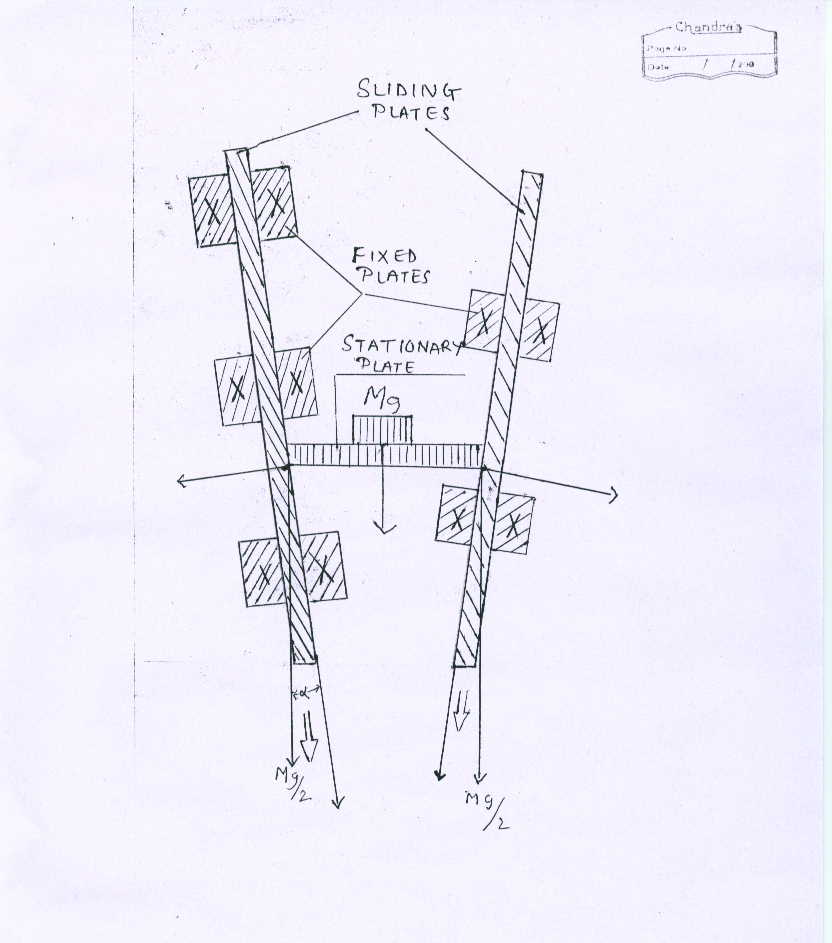
As shown in figure (energyefficiency1.jpg) sliding plates can slide over fixed plates. Stationary plate is simply supported horizontaly on sliding plates. Lubrication is provided at contact surfaces of stationary plate and sliding plates. Weight or load or force (mg) is applied at center of stationary plate. This load is equally devided and applied on each sliding plate in vertical downward direction (mg/2). This mg/2 cos(alpha) helps sliding plate to slide in nearly downward direction.
Force is stationary and it can help to slide the sliding plates.
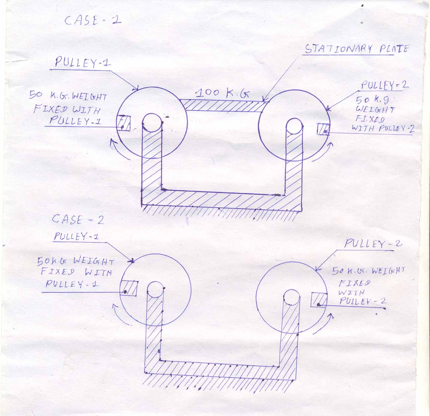
The figure(energyefficiency.jpg) is in cross section. as shown in figure, there are two cases. in each case there are two pulleys of same diameter. each pulley is of exactly circular shape.In first case 50 k.g weight is fixed with each pulley as shown in figure. The center of each pulley is fixed. Between these two pulleys there is a stationary plate. plate will remain stationary, while rotating the pulleys because centers of pulleys are fixed. 100 k.g weight is put on this plate. The force or weight of plate is applied on these two pulleys in vertical downward direction. now we try to rotate slowly first pulley in clockwise direction and second pulley in anti clockwise direction. lubrication is provided between the contact surfaces of stationary plate and pulleys.
In second case two pulleys of same diameter. 50 k.g weight is also fixed with each pulley, but there is no stationary plate and 100 k.g weight. Now we try to rotate slowly first pulley in clockwise direction and second pulley in anti clockwise direction.
As free body diagram in first case we can rotate pulleys using less moment of force. we can lift mass using less energy.
1. In case 1) the moment necessary to rotate each pulley is
m=(-g/2cos(bita)+g1*cos(alpha))*r
where:
g is weight of plate (=100 kg)
g1 is given weight (=50 kg)
alpha and bita are angle of rotation of each pulley
r is radius of pulley
2. In case 2) weigt of plate g=0
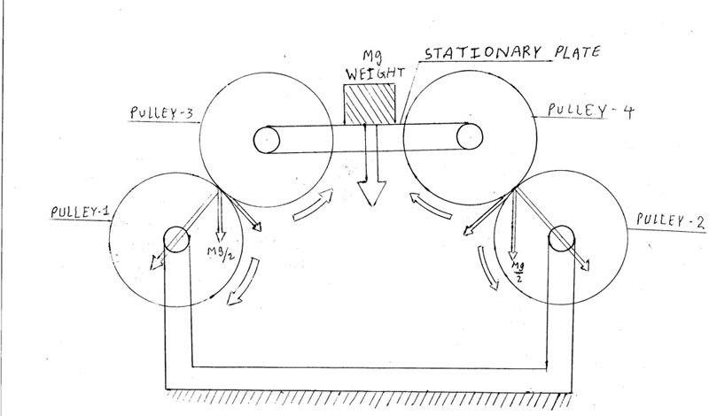
Cross section of pulley1, pulley2 , pulley3 and pulley4 are as shown in figure(energy.jpg). Center of Pulley 1 and pulley 2 are placed on same horizontal line. Center of pulley 1 and pulley 2 are fixed. Pulley 1 and pulley 2 can rotate about their center. Center of pulley3 and pulley4 are also placed on one horizontal line. Pulley 3 and pulley 4 can also rotate about their center. Center of pulley 3 and pulley4 are joined with one stationary plate.Pulley 3 and pulley4 are simply supported on pulley1 and pulley2.Now we apply some load or weight on stationary plate. Finaly this force is applied on pulley 1 and pulley 2 in vertical downward direction because pulley 3 and pulley4 are simply supported on pulley 1 and pulley2. Tangential componants of these force helps to rotate pulley1 , pulley2 , pulley3 and pulley4. If you want to remove pulley3 and pulley4 , stationary plate is directly simply supported on pulley1 and pulley2 then also pulley1 and pulley2 can be rotated.
| Attachment | Size |
|---|---|
| energyefficiency.jpg | 123.31 KB |
| energy.jpg | 58.09 KB |
| energyefficiency1.jpg | 47.53 KB |