
A two-dimensional stress transfer model for platelet reinforcement, Hsueh, Composites Engineering, 1994
Significance:
Despite a few citations, this work provides classical analysis of the stress transfer problem in platelet-reinforced composites, the derivations of the platelet axial stress and interfacial shear stress distributions considering effects of the ends bonding/debonding and the matrix axial stress varying axially and transversely.
The method/thought is clear, rigorous, and applicable, which has been used concretely in studies on engineering platelet-reinforced composite mechanics [Haque and Ranasetty 2005] and also biological composites with stagger-aligned platelets [Kotha et al., 2001].
Mechanics of fiber reinforcement based on shear-lag theories have been abundant, while stress transfer for platelet reinforcement is not well-established; existing models either follow the same way as Cox’s shear-lag [Tyson and Davies 1965] or lack description of the variations of axial stress and interfacial shear stress [Piggott 1980].
Goal: For two scenarios (I) platelet ends debonded and (II) platelet ends bonded to the matrix, determine the (1) axial platelet stress distribution, (2) the matrix-platelet interfacial shear stress distribution (within and beyond the platelet length), (3) the effects of the end bonding, modulus ratio, and aspect ratio on the stress distributions;
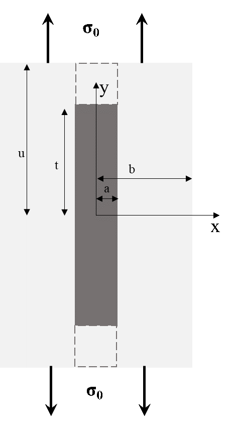
Assumptions: platelet and matrix behave elastically; the platelet plane is bonded to the matrix with perfect interface bonding; a unit cell is shown in Fig.1, an idealized two-dimensional model (the platelet dimension normal to the x-y plane is much greater than a, and is not included); the platelet ends can be debonded (by Mode I crack opending) and bonded to the matrix (by using imaginary matrix platelets technique);
Model/the physical process: a platelet with finite length is embedded in matrix. Upon external stress σ0, the matrix transfers stress to the platelet through the interfacial shear stress, τi, at x=± a; the matrix edges are free surface, meaning x=b, τb=0.
The platelet axial stress varies along y but is uniform along x; different from classical shear-lag in cylindrical geometry in which only stress variation in the loading direction is considered, the matrix shear stress varying along axial and transverse directions are included.
Fig. 1. The unit cell.
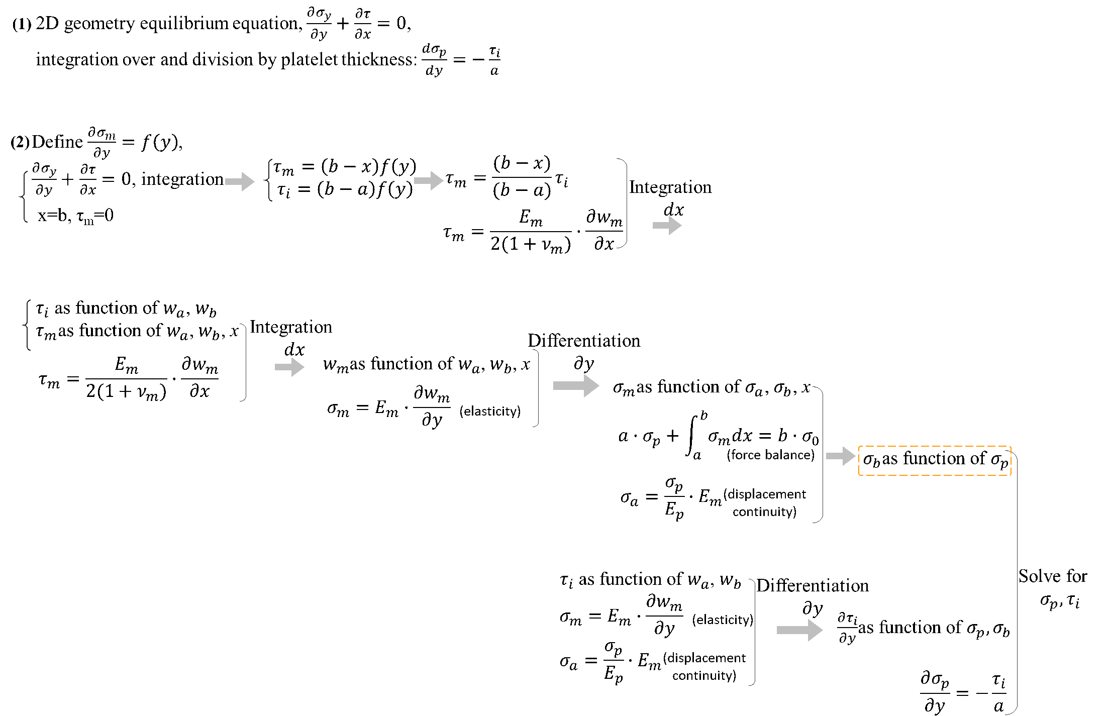
Route:
Fig. 2. Flow chart of the derivation steps (1) and (2).
(3) For debonded ends, at y=t, platelet axial stress=0; at y=0, interfacial shear stress=0, then expressions for platelet axial stress and interfacial shear stress are determined (within platelet length region). By using a 2D crack problem [Sneddon 1969], the interfacial shear stress beyond the platelet length region can be predicted.
For the bonded ends, the matrix above and below the platelet is treated as two imaginary platelets having the same properties as matrix; then with displacement continuity and appropriate boundary conditions, the platelet axial stress and interfacial shear stress are determined (within and beyond the platelet length regions).
Key steps/thoughts:
(1) Due to assuming matrix axial stress varying axially and transversely (more realistic), one more variable, matrix axial stress at x=b, is introduced, and needs to find another equation (orange dotted rectangle outlined in the flow chart in Route) to solve all the variables. This work shows an ingenious way which is applicable to other problems.
(2) Considering the two debonded ends as two cracks, then using Mode I crack opending can predict the shear stress beyond the platelet ends; for the bonded ends, a technique of adding fictitious platelets with matrix properties contacting the real platelet at ends is developed to solve for the platelet axial stress and interfacial shear stress distributions.
Results/discussion: (1) The present model is an improvement, based on comparisons among results from the present model, the existing model [Tyson and Davies 1965], experiments [Tyson and Davies 1965], and the 2D crack solution.
The present model predicts interfacial shear stresses that are closer to the experimental measurements than the existing model does; except at crack tip locations, interfacial shear stress from the present model show fair agreement with those from the classical solution. For bonded ends, beyond the platelet ends the matrix has finite values of axial stress and interfacial shear stress; when the loading surface is sufficiently remote from the platelet ends, both the axial stress and interfacial shear stress approach their asymptotic values.
(2) The Young’s moduli ratio, aspect ratio, and end bonding affect the stress transfer. For both bonded and debonded ends, increasing the ratio of platelet modulus over matrix modulus leads increased stress transfer (higher platelet axial stress) and faster changes of interfacial shear stress, while increasing aspect ratio also increases stress transfer. Bonded ends condition shows more effective stress transfer than the debonded scenario, and needs shorter length than the debonded condition to reach the maximum platelet axial stress.
One observation (not stated in the paper) is that the stress transfer increase from high aspect ratio can offset the decreasing effect by end debonding, that is, higher aspect ratio with debonded ends can generate higher platelet axial stresses faster than lower aspect ratio with bonded ends does (aspect ratio 20, deboned ends versus aspect ratio 10, bonded ends.
Here is the link of the fulltext: https://www.sciencedirect.com/science/article/abs/pii/S0961952609800051
References:
Haque, A., & Ramasetty, A. (2005). Theoretical study of stress transfer in carbon nanotube reinforced polymer matrix composites. Composite Structures, 71(1), 68-77.
Kotha, S. P., Li, Y., & Guzelsu, N. (2001). Micromechanical model of nacre tested in tension. Journal of materials science, 36(8).
Tyson, W. R., & Davies, G. J. (1965). A photoelastic study of the shear stresses associated with the transfer of stress during fibre reinforcement. British Journal of Applied Physics, 16(2), 199.
Piggott, M. (1980). Chapter 8 in Load Bearing Fibre Composites. 1st ed., Pergamon.
Sneddon, I. N. (1969). In Cracks Problems in the Classical Theory of Elasticity, p.29. John Wiley, New York.
| Attachment | Size |
|---|---|
| Fig.1. Unit cell. | 11.89 KB |
| Fig. 2. Flow chart of the derivation steps (1) and (2). | 63.89 KB |
The two important figures are
The two important figures are not properly shown in the main part, so both are attached.
It is believed that Fig.2 can provide clearly the derivation route.