Hi,
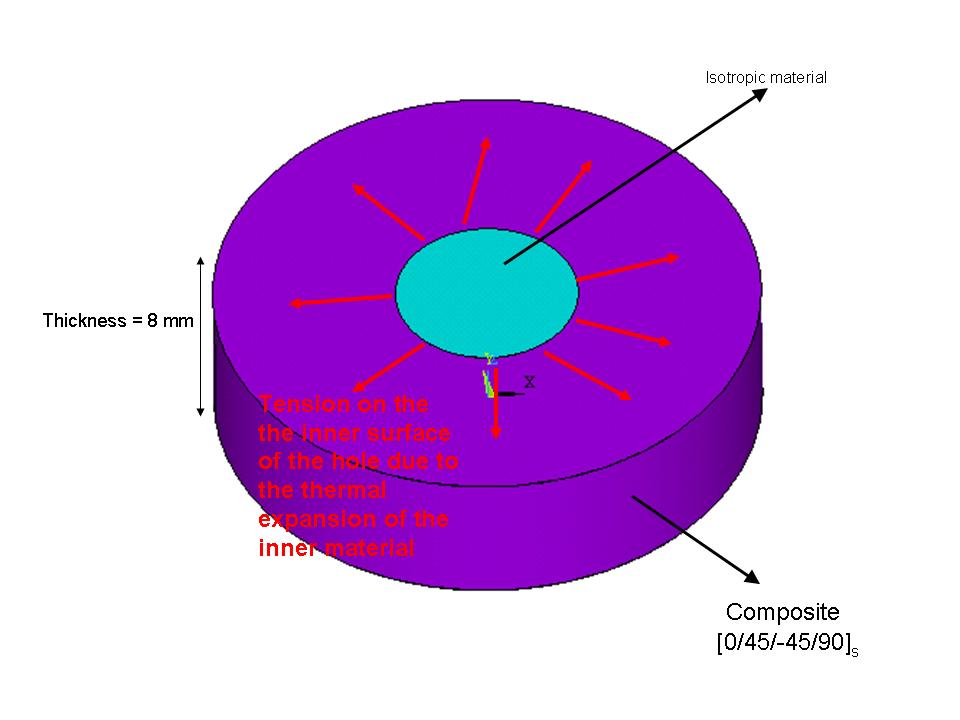
I am trying to model a composite material in ANSYS. I have used ANSYS for simple simulations before but I have never done composite material analysis. I have attached a simple schematic of what I am trying to model. Can you guys please help me? Any tip you can give will help. I have limited time.
Thank you,
Basak
| Attachment | Size |
|---|---|
| schematic1.JPG | 40.19 KB |
Should I use SOLID46 for the
Should I use SOLID46 for the outer material and SOLID45 for the inner material?
In reply to Should I use SOLID46 for the by Basak
how to do analysis in composite material using ansys
hi this is mukesh
You can, in principle,
You can, in principle, use SOLID46 for composite layers. It lets you define the orientation and material of each layer directly. But then your freedom to mesh as you want is hindered (as I remember you can have only one element per layer in SOLID46) and if you have a complex geometry, you would need a finer mesh.
On the other hand, you can always use SOLID45 elements even for composites. It will be more accurate. Just define the relevant material properties and use a different coordinate system (CSYS) to define orientation for each layer. So, for your case, you will have 5 such cylinders - 1 innermost for isotropic material and 4 for the 4 layers of composite material. Create the 3D model in this way, mesh it and define CSYS 21-24 (rectangular) with orientations 0,45,-45,90 etc. Select elements in each cylindrical layer and modify its CSYS and material to the required one.
e.g., Use this series of commands after defining an volume component for +45 layer:
1. cmsel,s,vol_p45 ==> Selects the volume vol_p45
2. alls,belo,volu ==> Select everything below selected volume (i.e. select elements)
3. local,21,1,0,0,0,0,0,0,45 ==> Define a cylindrical CSYS no. 21 rotated at 45 deg w.r.t. z-axis (you need to see how your lamina are oriented)
4. emodif,all,mat,2 ==> Modify all selected elements to have material no. 2
5. emodif,all,esys,21 ==> Modify the coordinate system for selected elements
Read these commands for details.
I hope this helps. Good luck!
----------------------------
Chandra Veer Singh,
Aerospace Engineering,
Texas A&M University
In reply to You can, in principle, by Chandra Veer Singh
help needed to analyse vibration in composite material
I'm SELVAKUMAR.G persuing M.E., in kongu engineering college taminadu.I too doing in vibration analysis for composite material using ANSYS.....so can u help how to analysis composite material using ANSYS....
Thank you!
Hi Chandra,
Thank you very much for your suggestions. They helped a lot! One quick question : What do you mean by one element per layer in SOLID46? Do you think my geometry is simple enough to still use SOLID46?
Thanks again,
Basak Oguz
Mechanical Engineering
Michigan State University
In reply to Thank you! by Basak
Chad has raised an
Chad has raised an important question. You can solve it using 2-D stress analysis, for which analytical solutions are avaialble.
However, if you want to do a 3-D analysis then:
Although this geometry is simple, I would suggest to use SOLID45.
Although you can get around "one element per layer issue in SOLID46" by
dividing a given layer into N imaginary sub-layers of same orientation
and thickness=layer thickness/N.SOLID46 can take upto 250 layers. SOLID46 is actually useful for modeling sandwitched structures with thin layers.
I have some modeling and formulation issues with SOLID46 in general
applications, e.g., if you have a variable layer thickness, what would
you do. SOLID45 are based on full 3-D formulation, so much better and
easier to use.
Using SOLID45 and refined meshing with current computational
power shouldn't be a problem. But you need to make sure that you define
and orient CSYS correctly. Once you understand this approach, you can
model complex geometry as well.
Chandra Veer Singh,
Aerospace Engineering,
Texas A&M University
In reply to Chad has raised an by Chandra Veer Singh
SOLID46
Hi Chandra,
I am kind of confused with the "one element per layer" thing. Ansys says that you can use upto 250 layers/element with SOLID46. Today I tried 80 layers per element (each layer 10 microns) and it worked. I am using an element size of 0.0008 on my mesh which gives me a total of 800 layers in the whole geometry. Am I getting the idea wrong?
Thanks,
Basak
Question
Basak,
Why do you want to analyze this geometry with finite elements? The geometry and loading that are shown in the picture are simple enough to study analytically. That is unless you are treating this as a 3D problem.
Chad
In reply to Question by Chad Landis
I agree unless Basak has
I agree unless Basak has some specific reason (loading/geometry) to warrant a 3-D analysis.
Chandra
In reply to I agree unless Basak has by Chandra Veer Singh
how to do analysis in composite material using ansys
hi this is mukesh
In reply to Question by Chad Landis
why FEA
Hi Chad,
We are treating this as a 3D problem and we would also like to find out the best composite lay-up that will give the least amount of stresses on the hole. I will not be doing only [0/45/-45/90]s. I will try out a bunch of different combinations.
In reply to why FEA by Basak
What stresses are you interested in?
In reply to What stresses are you interested in? by Chad Landis
need help in composite analysis
hello Sir.
I m new to composite analysis in ansys. I m doing a project of wind turbine analysis. The lay-up contains 46 layers of UD, 46 layers of DB, spar and coreform between the suction side and presure side of one blade. For modelling the layers i m using mid-surface of the total thickness of the layer in the form of surface and i don't understand about the bonding betwen the layers, means we have to create any special type of elements between the layers for bonding. I am very thankfull to u for your guidence...........
Interface elements on a similar model
.
element properties for glass fiber and epoxy
hi i am doing project on delamination analysis of composite material in ansys 10...i am using glass fiber and epoxy and i dont know the correct element properties of both the composite and epoxy.pls help me to show any full tutorial of that or give any suggestions........layers = 8, density of fiber = 220gm/cc, lenght = 125 mm, delamination crack = 50 mm, thickness = 4.5mm...help me to do analysis..or send your suggestions on murugesan_kpm [at] yahoo.com (murugesan_kpm[at]yahoo[dot]com)
It is a misconception that
It is a misconception that 3D analysis is needed for inter-laminar shear stresses. In fact, if you use VABS , then you can still use your simple 1D beam theory but with the capability to obtain the complete 3D strain field. For geometrical linear analysis of a clamped blade, the 1D results can be worked out analytically. You do need a cross-sectional mesh for VABS to help you reduce the 3D model into a 1D beam model and recover the 3D fields from 1D results.
composite modeling
hi i want to do impact test of composite made up from glass fiber epoxy and aluminum in ansys ls-dyna please tell me what damage material model i should use to do so