
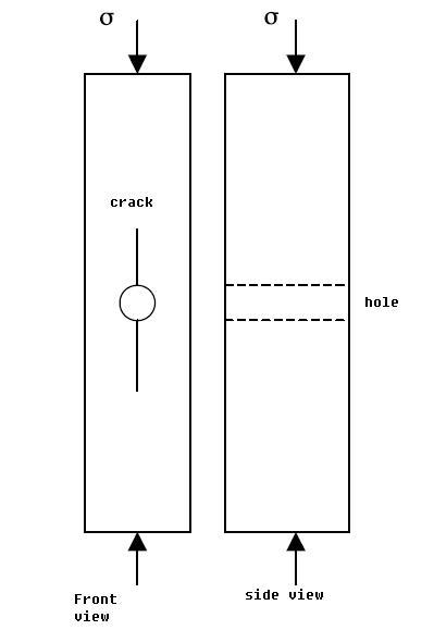
Double cleavage drilled compression (DCDC) specimen is widely used for fracture toughness measurment of brittle materials. As shown in attached figure, the DCDC specimen is rectangular in cross-section with a circular hole drilled through the center. In compression, at some critical stress level, symmetrical cracks will initiate and develop in opposite directions along the mid-plane of the specimen. The mode I stress intensity factor in DCDC specimens is a function of crack length besides other factors, therefore requires the measurement of crack length in the loading process, usually by optical observation of the crack front. I wonder if there is any other way to measure the crack length, for example by measuring structure compliance with a partial unloading, or electric method. Any suggestions will be appreciated.
| Attachment | Size |
|---|---|
| DCDC.JPG | 13.28 KB |
eddy currents
Sounds like an eddy current method would be best?
http://en.wikipedia.org/wiki/Eddy-Current_Testing
Li Han
Li Han
re: eddy currents
Mark, thanks for pointing out EC method. I followed up your link and it appeared to me that EC method is well suited for detecting the presence of surface crack (as small as 0.1mm). However, I have not found how EC can be used to quantify the length of crack. Am I missing something here ?
Li Han
Re: Eddy Currents
I *still* don't find the time to once again become active at iMechanica, but I will make an exception here... You see, in one of my past lives, I used to be an eddy currents application engineer.
What is the material? If nonconducting, eddy currents won't work. (I suspect it's nonconducting because you say it's brittle and test it in compression.)
For your problem, even if the material is conducting, eddy currents may not be ideal. The potential drop method might be better. In general, though, at least until early 1990s, people used to sometimes use compliance (relax the loading a bit for measuring crack length) method.
If you could please come back with more details of material, test specimen (size), test purpose, loading rate, etc. I could suggest further problems/pitfalls to be aware of and the alternatives available...
more details
Dear Ajit, thanks for the special favor :)
The objective of study is to measure the adhesion between the film and
substrate whatever method in quasi-static condition. The substrate material is
semiconductive, non-transparent, brittle, no bigger than 1 inch* 1 inch and is
about 1mm thick. Miniaturized 4point bend flexture is an option, but small
sample is difficult to handle stably. DCDC is another option, but require
measure of crack length.
Li Han
In reply to more details by Li Han
Re: more details
Dear Li,
Nope. No special favors.... I just thought that this being an applications topic, I could just offer my advise once and escape. In contrast, if a thread touches on very complex or very deep *theoretical* notions, as against direct applications, one has to give a lot more attention to the logic that is oftentimes kept only implicit in other peoples' arguments. This takes time... And, then, sometimes the discussion slides onto something else... In contrast, yours was a very specific query.
-----
One would have liked to know the substrate (thin film) material as well. Also, if you would expect delamination of the substrate...
But leaving aside these considerations, and without really dwelling into *all* the reasons why I think so, I think your best bet is to directly observe the crack and measure its length (perhaps also observe its growth) using a special optical microscope that is mounted right on the frame of the testing machine. This way of measuring the crack length could be your primary method. I would make sure that the crack lengh readings obtained this way made reasonable sense, using the compliance method also. Off-hand, I would expect the compliance method to carry less of a resolution in crack length, but it could be more fail-proof in showing up in its results that the crack has actually extended. This could be your secondary method for crack *length* measurements.
Using a microscope will also allow you to better monitor any other interesting phenomena such as delamination, branching, etc. (One way or the other, I think you will be polishing the specimens as in the metallurgical specimen preparation.)
Also, think of using a suitable dye penetrant. It might not *detect* a crack if one is not already visible under microscope, but the use of a dye *should* help *delineate* the crack. (People sometimes show this kind a macrograph or a low resolution micrograph in their papers.)
Among other methods, I could be wrong, but my immediate judgment is that eddy current NDT would not have the required sensitivity for the semiconductor material.
The potential drop (PD) method might not be suitable for such a small specimen. But do check the literature out, they might have smaller and finer sensors developed these days. (Instrumentation engineering too progresses amazingly rapidly.) The con against PD method in your case is that the noise due to contacts might overwhelm the signal arising due to micro extension of micro-crack-tip.
Best wishes, (and once you finish your experimentation, please do update us on the method you found suitable and actually used),
Ajit