
Bio-Inspired 3D Printed Sutures under Shear
Richard Nash and Yaning Li*
Department of Mechanical and Industrial Engineering, Northeastern University, MA
* y.li [at] northeastern.edu
Modified from the following paper:Richard J. Nash and Yaning Li, Experimental and numerical analysis of 3D printed suture joints under shearing load, Engineering Fracture Mechanics (2021), Vol. 253, 107912
https://doi.org/10.1016/j.engfracmech.2021.107912
1. Introduction
In many engineering fields such as bio-medical engineering, aerospace and automotive engineering, the need for lighter and stronger composite materials is increasing. In designing lightweight composites, interfacial properties are often the key to determine the overall stiffness, strength and toughness of the composites [1-7]. For example, for biomedical implants, dissimilar joints/intefaces offer unique advantages in providing both high deformability and high abrasive resistance. However, a critical issue for the reliability of engineering dissimilar joints is the lack of interfacial bonding between dissimilar materials, which limits the mechanical performance of the material [1-4,8].
The bio-inspired strategies can be applied to engineer artificial dissimilar joints [26-35]. However, it is challenging to fabricate bio-inspired dissimilar joints with complicated geometry via traditional manufacturing technologies [36, 37]. Additive manufacturing is a promising new technology to meet this challenge. Additive manufacturing (AM) provides a fast, accurate, and repeatable way to fabricate the biomimetic designs. In order to fabricate dissimilar joints, multi-material additive manufacturing technology is needed. In multi-material additive manufacturing, improving interfacial bonding continues to be a challenge. Currently, it is not well understood how processing parameters, such as printing speed and directions, will influence the quality of the printed products.
2. Mechanical experiments
2.1 Manufacturing and single lap shear experiments
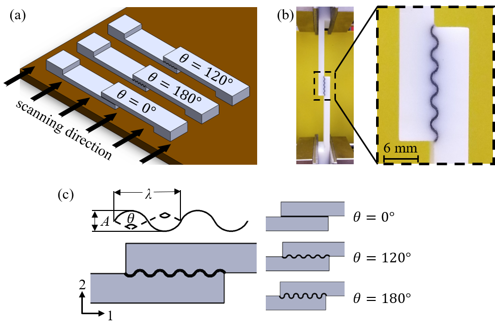
The specimens were manufactured via additive manufacturing (AM) by utilizing the Stratasys Objet260 Connex3 multi-material 3D printer. The phase 0 (Fig. 1a) material in the interfacial layer was printed as TangoBlack, a softer, rubber like material; while phase 1 was printed as VeroWhite, a harder plastic material. The orientation of the specimens were chosen arbitrarily initially but kept consistent from then on and the printing direction are shown in Fig. 1a.
Fig. 1. (a) The arrangement of the three specimens on the tray of the 3D printer and the printing direction; (b) a representative image of the experimental setup of the specimen with θ=120°; (c) the suture zones of the three specimens with θ=0o, 120o, and 180o.
Each specimen was mounted on a Zwick Material Testing Machine. A uni-axial tensile displacement with the quasi-static loading rate of 0.025 mm/min was applied. The experimental setup is shown in Fig. 2b where the bottom of the specimen is secured in stationary grips while the top of the specimen is secured in displacement-controlled grips that are mounted to a 10 KN load cell. For repeatability, for each design, three identical specimens were printed and tested. So total nine experiments were performed.
2.2 Failure Mechanisms
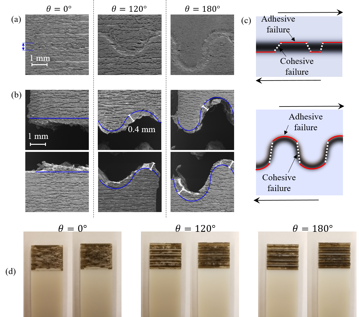
To further explore the failure mechanisms of the 3D printed flat and wavy interfacial layer under the shearing load, the surfaces of the undamaged and damaged specimens were observed under Scanning Electron Microscope (SEM, Tescan Lyra3 GMU combined FE-SEM/FIB field emission microscope). After the mechanical experiments, the damaged specimens were carefully removed from the material testing machine and stored in a closed box before the SEM tests. For comparing with the damaged specimens, new specimens without any damage were printed for similar SEM tests. The SEM images of the surfaces of the undamaged and damaged specimens in the zone around the interfacial layers are shown in Fig. 2a and 2b, respectively.
The horizontal grooves on the SEM images shown in Fig. 2a are induced by the layer-by-layer additive manufacturing process, indicating the printing direction shown in Fig. 1a. As shown in Fig. 2a, for the undamaged specimens, the boundary between phase 0 and phase 1 can be identified.
For the damaged specimens, adhesive failure is dominant, although both adhesive failure and cohesive failure are observed along the interfacial layer. As depicted in Fig. 2c, adhesive failure occurs when the two neighboring phases debond, while cohesive failure occurs when material within the interfacial layer fails. The photos of the fracture surfaces of the three designs are shown in Fig.2d. The lighter spots on each image indicate adhesive failure between VeroWhite material and TangoBlack material.
Fig. 2. (a) SEM images of the three specimens before mechanical experiments; (b) SEM images of the three specimens after mechanical experiments; (c) schematics depicting the combined adhesive and cohesive failure mechanisms in flat and wavy interfacial layers under the shearing load. (d) photos of the facture surfaces of the three designs, indicating adhesive failure modes.
2.3 Effects of printing direction
Due to the layer-by-layer additive manufacturing process, it is expected that the printing direction will influence the mechanical properties and behaviors of the interfacial layer and therefore the overall shear stiffness and strength of the specimens.
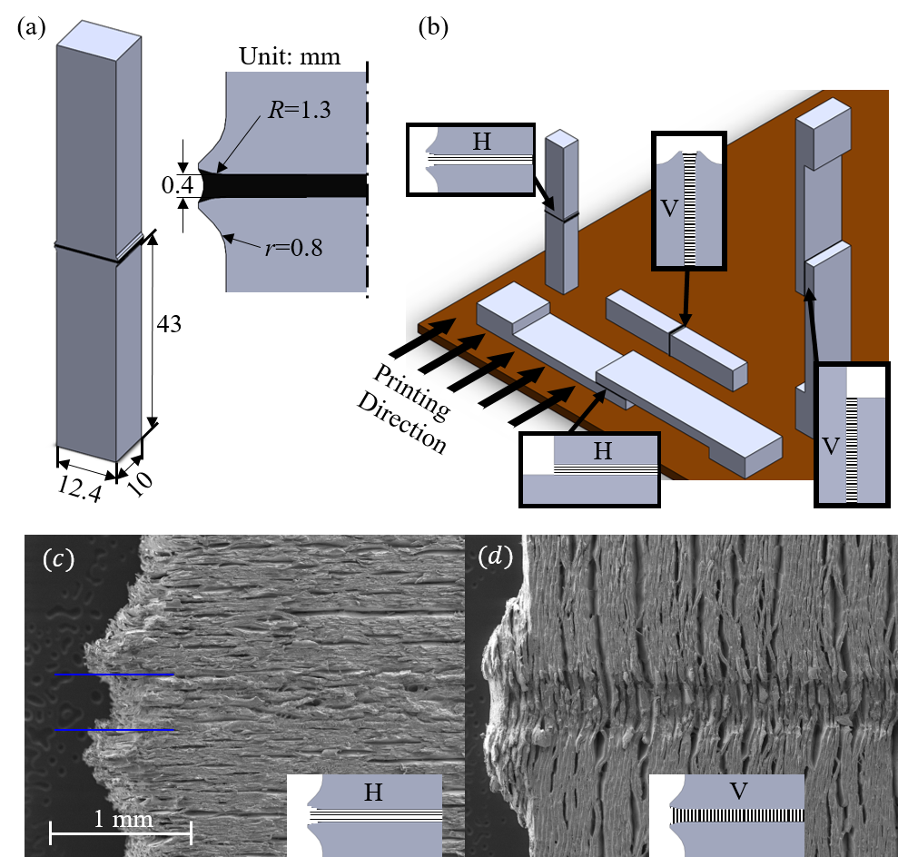
Total four types of specimens were printed, as shown in Fig. 3b: uni-axial tension specimens with printing directions H and V, respectively; and the single lap shear specimens with printing direction H and V, respectively. For repeatability, three to five identical specimens were printed for each type, total fifteen specimens were printed for this study.
The SEM images of the uni-axial tension specimens with two different printing directions are shown in Figs. 3c and 3d. Fig. 3a shows the SEM image of the uni-axial tension specimen fabricated with H printing direction, as shown in Fig. 3b, and Fig. 3b shows the SEM image of the same design fabricated with the V printing direction, as shown in Fig. 3b. Figs. 3a and 3b clearly show the different micro-scale surface textures of the specimens fabricated along the two different printing directions.
Fig. 3. (a) A SOLIDWORKS model of the tensile specimen designed to determine the material properties (the beaks at the free edges follows the design by Liu and Li [27]; (b) the four types of specimens that are required to determine the material properties for each printing direction and their orientation on the build plate; SEM images of the undamaged uni-axial tension specimens fabricated with: (c) the H printing direction; and (d) the V printing direction.
3. Finite element simulations
3.1 Finite element models
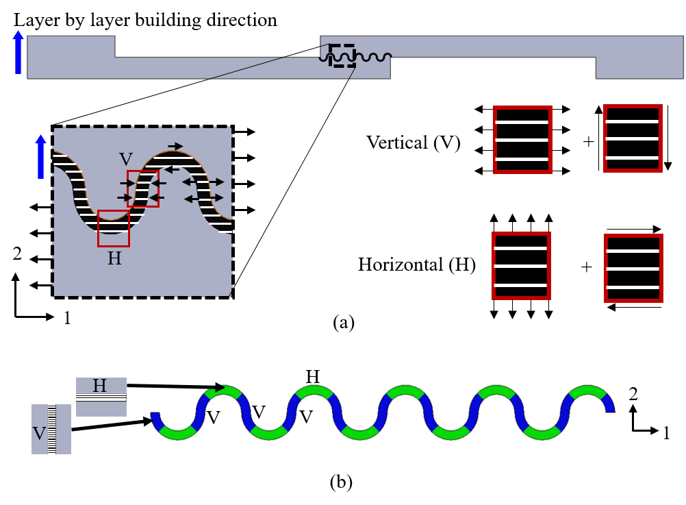
The two dimensional geometries of the specimens with θ=0°, 120° and 180° are created in ABAQUS/CAE (Version 6.14). In order to model the influences of printing direction, the interfacial layers are separated into H zone and V zone, as schematically shown in Figs. 4a and 4b. As illustrated in Fig. 4a, this is because that under the overall shearing load, near the peaks and valleys, the interfacial layers are mainly under normal stress perpendicular to the layered grooves and shear stress parallel to the layered grooves and therefore behaves similar to the interfacial layers with H printing direction shown in Fig. 4b; while the interfacial layers between the peak and valley zones are approximately under the normal stress parallel to the layered grooves and shear stress perpendicular to the layered grooves, and thus function similarly to the interfacial layers with V printing direction shown in Fig. 4b. As shown in Fig. 4b, for both wavy specimens, each H zone and V zone occupies one quarter of the full wavelength along the interfacial layer. This assumption was one limited by both time and materials for testing, and because the current tools in ABAQUS do not yet allow for a continuously changing material property along the suture at different angles. Different mechanical properties will be defined in H and V zones. The mechanical properties will be determined based on the experimental results.
Fig. 4. (a) Schematics depicting the mechanical functions of H and V zones, and (b) the partitioned interfacial layer (by taking the θ=180° case as an example), showing the H zones and the V zones.
3.2 FE simulation results
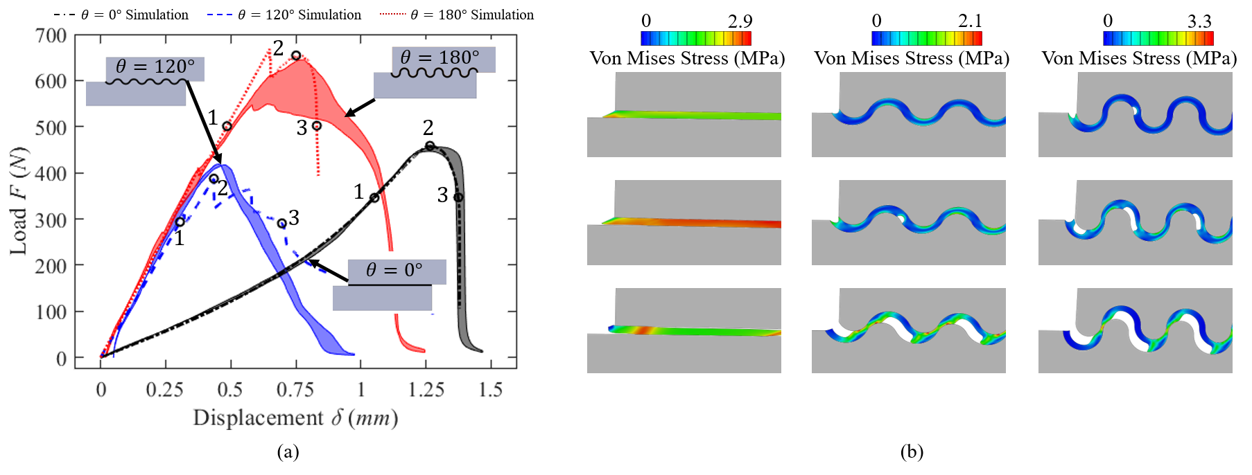
The load-displacement curves from the simulations are compared with the experimental data in Fig. 5a. For each simulation, the von Mises stress contours within the interfacial layer at three different instants are shown in Fig. 5b. The three instants, 1, 2, and 3 are marked on the load-displacement curves in Fig. 5a. Instant 2 is taken at the peak load; instant 1 is taken at 75% peak load before the peak; and instant 3 is taken at 75% peak load after the peak.
Fig. 5. The comparison between the experimental and simulation load-displacement results (points 1, 2, and 3 on each curve represent the instants at 75% peak load before the peak, at the peak, and at 75% peak load after the peak, respectively; and (b) the von Mises stress contours in the interfacial layers at instants 1, 2 and 3.
It can be seen that for the case of θ=0°, the simulation results match with experimental results very well. Since the layer is flat, the material in the layer is mainly under a simple shear stress state and the mechanical behaviors of the layer in this simple stress state are accurately captured. For the wavy cases, the material in the layer is under a complicated mixed Mode I/II loading. Before damage initiation, the simulation results match with the experimental results very well. But when damage initiates, discrepancies are observed between the simulation and experimental results.
4. Conclusions and discussion
First, the experimental and simulation results show that by increasing the waviness of the suture layer, the effective shear stiffness of the joints can be significantly increased. For the specific designs in this paper, the wavy sutures can achieve an effective shear stiffness more than 10-20 times larger than that of the flat one. However, in order to significantly increase the overall shear strength of the joints, the waviness needs to be large enough. For example, for the case of θ=120°, the effective shear strength is almost the same at that of the flat layer, while when θ increases to 180°, the effective shear strength increases for about 40%.
Also, the experimental results show that the printing direction have non-negligible influences on the shear and tensile strength of the 3D printed interfacial layer fabricated via the layer-by-layer material jetting additive manufacturing technology. But the effective shear and tensile stiffnesses are barely influenced by the printing direction. Generally, when printing the dissimilar interface, if the layer orientation is parallel to the interface (i.e. the H direction in this paper), higher shear and tensile bonding strength can be achieved. While, if the layer orientation is perpendicular to the interface, shear and tensile bonding strength will be lower. Specifically, for the single lap shear specimen and the tensile specimen in this paper, when the specimens are printed with H direction, the overall effective shear strength of the interfacial layer is about 14.5% higher than that printed with V direction; and the overall effective tensile strength of the specimen is about 14.7% higher than that printed with V direction.
In addition, this investigation shows that the method used is promising in predicting the mixed mode damage initiation and evolution of dissimilar joints dominated by adhesive failure mode under either shear or tensile loads. More accurate prediction can be achieved by incorporating both the damage evolution along the out-of-plane direction and the cohesive failure mode within the interfacial layer.
References
[1] Martinsen K, Hu S, Carlson B. Joining of dissimilar materials. CIRP Annals. 2015;64:679-99.
[2] Amancio-Filho S, dos Santos J. Joining of polymers and polymer-metal hybrid structures: Recent developments and trends. Polym Eng Sci. 2009;49:1461-76.
[3] Li Y, Waas AM, and Arruda EM, A closed-form, hierarchical, multi-interphase model for composites --derivation, verification and application to nanocomposites, Journal of Mechanics and Physics of Solids 2011;59:43-63.
[4] Li Y, Waas AM, and Arruda EM, The effect of interphase and strain gradients on the elasticity of LBL polymer/clay nanocomposites, International Journal of Solids and Structures 2011;48:1044-1053.
[5] Li Y, Kaynia N, Rudykh S, and Boyce, Wrinkling of interfacial layers in stratified composites, Advanced Engineering Materials 2013;15(10):921-926.
[6] Gao C and Li Y, Tuning the wrinkling patterns of an interfacial/coating layer via a regulation interphase, International Journal of Solids and Structures 2017;104-105:92-102.
[7] Gao C, Slesarenko S, Boyce MC, Rudykh S and Li Y, Instability-Induced Pattern Transformation in Soft Metamaterial with Hexagonal Networks for Tunable Wave Propagation, Scientific Reports 2018;8:11834.
[8] Meiss E. Adhesive Bonding – Advantages and Limitations. Biuletyn Instytutu Spawalnictwa. The Institute of Welding. 2014;24-6.
[9] Hubbard R, Melvin J, Barodawa I. Flexure of Cranial Sutures. J Biomech. 1971;4:491-496.
[10] Song J, Reichert S, Kallai I, Gazit D, Wund M, Boyce M, Ortiz C. Quantitative microstructural studies of the armor of the marine threespine stickleback (Gasterosteus aculeatus). J Struct Biol. 2010;171(3):318-331.
[11] Liu L, Jiang Y, Boyce M, Ortiz C, Baur J, Song J, Li Y, The effects of morphological irregularity on the mechanical behavior of interdigitated biological sutures under tension. J Biomech. 2017;58:71-8.
[12] Barthelat F, Tang H, Zavattieri PD, Li CM, Espinosa HD, On the mechanics of mother-of-pearl: a key feature in the material hierarchical structure, J. Mech. Phys. Solids. 2007; 55 (2): 306-337.
[13] Sun J, Bhushan B. Hierarchical structure and mechanical properties of nacre: a review. RSC Advances. 2012;2.
[14] Inoue S, Kondo S. Suture pattern formation in ammonites and the unknown rear mantle structure. Sci Rep. 2016;6:33689.
[15] Hasseldine BPJ, Gao C, Collins JM, Jung HD, Jang TS, Song J, et al. Mechanical response of common millet (Panicum miliaceum) seeds under quasi-static compression: Experiments and modeling. J Mech Behav Biomed Mater. 2017;73:102-13.
[16] Gao C, Hasseldine BPJ, Li L, Weaver J, Li Y. Amplifying Strength, Toughness, and Auxeticity via Wavy Sutural Tessellation in Plant Seedcoats. Adv Mater. 2018;1800579.
[17] Hasseldine BPJ, Gao C, Li Y. Prediction of the anisotropic damage evolution of dry common millet (Panicum miliaceum) seed under quasi-static blunt indentation. Eng Fract Mech. 2019;214:112-22.
[18] Gao C, Li Y. Mechanical model of bio-inspired composites with sutural tessellation. J Mech Phys Solids. 2019;122:190-204.
[19] Li Y, Oritz C, Boyce M. Stiffness and strength of suture joints in nature. American Physical Society, Physical Review E. 2011;84:062904.
[20] Li Y, Oritz C, Boyce M. A bio-inspired mechanical, deterministic fractal model for hierarchical suture joints, Physical Review E. 2012;85, 031901.
[21] Li Y, Ortiz C, Boyce M. A generalized mechanical model for suture interfaces of arbitrary geometry. J Mech Phys Solids. 2013;61(4):1144-1167.
[22] De Blasio FV. The role of suture complexity in diminishing strain and stress in ammonoid phragmocones. Lethaia. 2008;41:15-24.
[23] Chen I, Yang W, Meyers M. Leatherback sea turtle shell: A tough and flexible biological design. Acta Biomater. 2015;28:2-12.
[24] Lee N, Horstemeyer MF, Rhee H, Nabors B, Liao J, Williams LN. Hierarchical multiscale structure-property relationships of the red-bellied woodpecker (Melanerpes carolinus) beak. J R Soc Interface. 2014;11:20140274.
[25] Zhang Y, Yao H, Ortiz C, Xu J, Dao M. Bio-Inspired Interfacial Strengthening Strategy Through Geometrically Interlocking Designs. SciVerse ScienceDirect. 2012;15:70-77.
[26] Nash R, Pruyn T, Chaput H, Li Y. Mechanical behavior of Bio-inspired wavy adhesive bonding under shear. ASME/IMECE Proceeding. 2017;71791
[27] Liu L, Li Y. Predicting the mixed-mode I/II spatial damage propagation along 3D-printed soft interfacial layer via a hyperelastic softening model. J Mech Phys Solids. 2018;116:17-32.
[28] Liu L, Li Y. Failure mechanism transition of 3D-printed biomimetic sutures. Eng Fract Mech. 2018;199:372-9.
[29] Miroshnichenko K, Liu L, Tsukrov I, Li Y. Mechanical model of suture joints with fibrous connective layer. J Mech Phys Solids. 2018;111:490-502.
[20] Khoshhesab MM, Li Y. Mechanical behavior of 3D printed biomimetic Koch fractal contact and interlocking. Extreme Mech Lett. 2018;24:58-65.
[31] Liu L, Li Y. A visco-hyperelastic softening model for predicting the strain rate effects of 3D-printed soft wavy interfacial layer. Mech Mater. 2019;137.
[32] Lin E, Li Y, Weaver J, Ortiz C, Boyce M. Tunability and enhancement of mechanical behavior with additively manufactured bio-inspired hierarchical suture interfaces. J Mat Res. 2014.
[33] Lin E, Li Y, Ortiz C, Boyce M. 3D printed, bio-inspired prototypes and analytical models for structured suture interfaces with geometrically-tuned deformation and failure behavior. J Mech Phys Solids. 2014;73:166-182.
[34] Libanori R, Carnelli D, Rothfuchs N, Binelli M, Zanini M, Nicoleau L, Feichtenschlager B, Albrecht G, Studart A. Composites Reinforced via Mechanical Interlocking of Surface Roughened Microplatelets within Ductile and Brittle Matrices. Bioinspiration Biomimetics. 2016.
[35] Djumas L, Molotnikov A, Simon G, Estrin Y. Enhanced Mechanical Performance of Bio-Inspired Hybrid Structures Utilizing Topological Interlocking Geometry. Sci Rep. 2016.
[36] Stuart T, Crouch I. The Design, Testing and Evaluation of Adhesively Bonded, Interlocking, Tapered Joints Between Thick Aluminum Alloy Plates. Int J Adhes Adhes. 1992;12(1):3-8.
[37] Matsuzaki R, Tsukamoto N, Taniguchi J. Mechanical Interlocking by Imprinting of Undercut Micropatterns for Improving Adhesive Strength of Polypropylene. Int J Adhes Adhes. 2016;68:124-132.