
The Ruga Mechanics
Prepared by Mazen Diab, Ruike Zhao and Kyung-Suk Kim
Brown University, Providence, RI
Introduction
The ‘ruga’, a Latin term, means a single state of various corrugated material configurations, which form diverse 2D-patterns on solid surfaces, interfaces and in thin films. Typical ruga configurations include large-amplitude wrinkles, creases, folds, ridges, wrinklons, crinkles and crumples. While rugae (plural of ruga) in Latin originally meant variety of corrugated configurations, it has been narrowly used in anatomy. In a broad sense, ruga structures are widely observed in Nature. They are on human, animal and plant skins, in the wings of insects, the surface of our brains, even the crust of the earth, the moon and the planets (Figure 1).
Ruga configurations have distinct geometrical characteristics, and each of them stands for an energetically monomorphic equilibrium configuration representing a single phase of ruga. Over the past half century important ruga phases have been identified – Biot for wrinkle [1], Gent & Cho / Hohlfeld & Mahadevan / Hong, et al. for crease [2, 72-74], Brau, et al. for period multiplication [3, 4], Sun, et al. & Pocivavsek, et al. for fold [5, 6], Cao and Hutchinson for ridge [7], Bowden, et al. for 2D wrinkles [8], Efimenko, et al. for hierarchical wrinkles [9], Ahmed, et al. for 2D ruga tessellation [10]. Diab, et al. recently constructed a comprehensive ruga phase diagram of a stiff surface boundary layer in a neo-Hookean solid (figure 2B) [11, 12]. They showed that, similar to conventional material phase transitions for which a thermodynamic potential typically depicts the behavior, ruga phase transitions are naturally described by bifurcation analysis with a mechanical (structural) potential. Construction of iso-periodic [11, 12] and self-selective ruga phase diagrams [13] will not only enable analysis for coexistence, scaling or localization of multiple ruga phases, etc., but will also provide understanding on meso-scale self-organizing mechanisms that can be controlled by large-scale field parameters.
Recently, importance of ruga mechanics in science and technology appealed to public – NPR and Discover Magazine. In an application point of view, there has been an increasing interest in developing new classes of multi-functional soft composite materials at various length scales. For example, since nano-science has advanced to produce various 2D materials beyond graphene [14-18], we expect that nano ruga-structures in such 2D materials can create unprecedented functional properties. For examples of relatively large-scale engineering applications, the ability to control ruga patterns makes soft composites useful in a wide range of applications such as soft robotics, flexible electronics, constructing artificial skins, and morphing aircrafts and marine structures [19-34]. In addition, principles of ruga phase formation will uncover important self-organizing phenomena in brain science [35-37], medical science [38, 39] and geo science [40-43].
Figure 1: You can also see it in the attachment below.
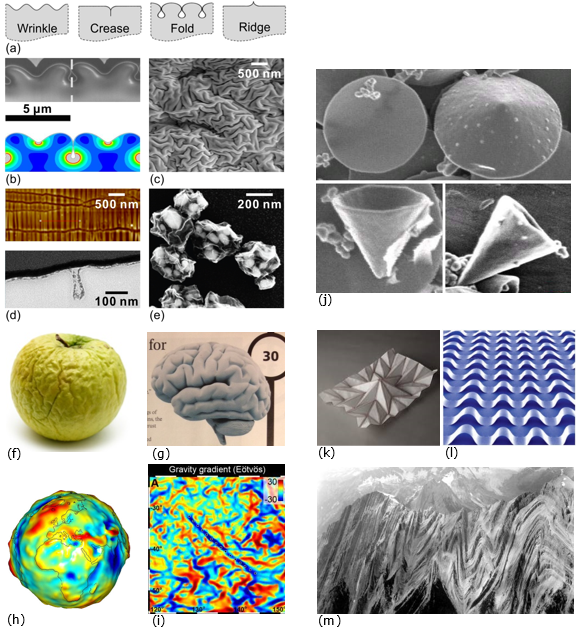
Figure 1: Ruga phases in nature and engineered materials: a) schematics of ruga phases in 1D structure; b) 50nm gold film folds: blue-red: 0-2 MPa Mises stress [5]; c) 2D ruga pattern on 10 nm ion beam implanted DLC on PDMS [158]; d) graphene folds, on PDMS (top & side views) [77]; e) graphene nano sacks with “cargos” [159]; f) 2D ruga patterns on a dry apple; g) brain cortex structure (from Discover); h) 3D mapping of local gravitational field strength of the earth; i) 2D ruga tessellation and localization of the gravitational field in the subsurface of the moon (500 km x 500 km view) (GRAIL mission); j) carbon disk (top left image) and free-standing hollow carbon nanocones [160, Wikipedia]; k) paper folding; l) nanoribbons for high Memory Storage Density; m) folded sedimentary layers of Sullivan River, British Columbia.
Mechanics of major ruga phases and their transitions:
Wrinkle:
Over the past several decades, mechanics research revealed that wrinkle has the following primary characteristics: 1) critical wavelength and critical strain, 2) distinct material property dependence, 3) weak imperfection sensitivity and stable amplitude growth. The research provided relatively simple relation among the critical wavelength, stiffness ratio and thickness. However, dependence of the relationship on material properties of the film and the substrate, and loading conditions including pre-stretch and finite deformation has been steadily and extensively investigated [1, 42, 44-64]. While the onset criticality of the wrinkling was analyzed by first-order perturbation, growth rate of the wrinkle amplitude and imperfection sensitivity of the criticality required higher-order-perturbation post-buckling analysis typically with the Koiter method [11, 12, 65-69]. The wrinkle characteristics of weak imperfection sensitivity and stable amplitude growth have been attractive features of wrinkle for experimental measurement of the property of the film relative to that of the substrate or vice versa [70, 71]. In addition, hierarchical wrinkles with their frequencies clustered in broad scales have been observed, and cause of the clustering has been debated [4, 9].
Crease:
In contrast to wrinkle, crease has other three distinct characteristics: localization of deformation, snap buckling with strong imperfection sensitivity and global irreversibility of deformation. For the first aspect, Gent & Cho [2], Hohfeld & Mahadevan [72, 74] and Hong, et al. [73] discovered the criticality and the mode of the crease localization. Later, Diab et al., [11, 12] uncovered that the crease localization is caused by cascade instability either from a fundamental state (instantaneous crease) or from a wrinkle state (setback crease). For the second aspect, a series of investigations [72-76] revealed that snap buckling of creasing is a consequence of bifurcation onto a branch of solutions extended from a subcritical state to a supercritical state. For the third aspect, the global irreversibility exhibits hysteresis in loading and unloading despite that the local deformation is elastic (reversible) everywhere [12, 74]. In addition, it is found that creasing is sensitive to imperfections [69].
Fold:
When wrinkle amplitude grows large, the wrinkles often form folds with high aspect ratio amplitude for self-contact, period multiplication of the wrinkle to set the fold periodicity, and subsequently leads to fold localization. The folds have attractive features for nano-manufacturing of surface nanostructures such as subsurface nano channels. Diverse characteristics of folding processes have been observed and investigated by several research groups. Those include folding of an elastic sheet floating on water [5], period multiplication of a wrinkle on a bilayer system [3], formation of periodic folds [6], folding of a graphene sheet on a PDMS [77], etc. The role of substrate nonlinearity in the post-buckling evolution of wrinkle has been revealed numerically by Sun, et al. [6] for fold, and further investigated by Hutchinson [68] and Zhao, et al. [13]. However, a quantitative characterization of the critical conditions for the large amplitude wrinkle evolution is still elusive due to lack of analytical expressions of the wrinkle configuration with nonlinear finite deformation at the onset of period multiplication. Once the wrinkle surfaces make self-contacts for folding, some selective fold tips begin to advance into the substrate with a series of unfolding of nearby folds, leading to fold localization.
Ridge:
Ridge is a ruga phase of localized bulge that exhibits mechanical characteristics similar to those of crease for localization and irreversible mode of hysteresis behavior. It is typically observed in a surface layer compressed by releasing a large pre-stretch strain. For example, depending on the level of pre-stretches of an incompressible neo-Hookean substrate, the wrinkle generally bifurcates to a single isolated ridge followed by development of periodic ridges through frequency multiplication followed by period multiplication. Ridges are formed through snap buckling and the configurational evolution is irreversible in general. Ridges often grow into ridge-folds at large compression of the film. ([13, 32, 69, 78, 79])
Delamination ruga:
Delamination ruga develops when a thin surface-mounted film with a relatively weak interface is laterally compressed to be debonded. Blistering and telephone cord buckling of a thin film mounted on a stiff substrate were extensively studied in 1990s. In contrast, when a stiff film is delaminated through wrinkling on a soft substrate, the delamination process develops localized delamination ridges. The delamination ridges often transforms into delamination folds under large strain mismatch, typically observed in CVD grown films of graphene caused by large thermal strain mismatch. Isolation of bending localization on the debonded part of the film has attracted attention for potential use of delamination ruga in flexible electronics applications. Recently a delamination ruga phase diagram was proposed. ([80-86])
Two-dimensional Ruga:
Experimental observations of various 2D ruga phases such as periodic checkerboard, herringbone, labyrinth, crease and fold have been reported [8, 87-93]. Recently Ahmed et al., [10] showed that for a strain larger than 30 % the folds evolve in random orientations to create asymmetric disordered tessellation. Wrinkle instability of hyper-elastic half space under general biaxial compression was studied by Nowinski [94], and Usmani and Beatty [95]. However, it was not until recently that the community started to investigate the formation of the various 2D ruga phases of bilayer systems using numerical and/or analytical approaches [55, 96-105]. Most all of these studies haven’t considered the full sequential bifurcations of the various patterns at large strains. Many issues are still unexplained such as the disordered tessellation observed in [10], the labyrinthine pattern, mode jumping, coexistent of states, and the role of imperfections on the formation of the ruga patterns. More efforts are needed to develop analytical and numerical tools that are capable of handling the formation of the complex 2D ruga phases and transitions among them.
Figure 2: You can also see it in the attachment below.
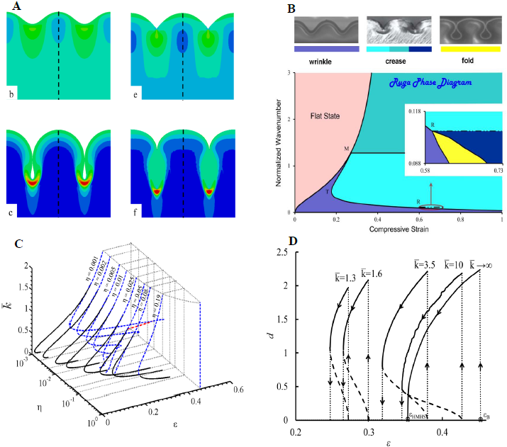
Figure 2: A) FEM results of 1D ruga phases [12]; B) ruga phase diagram of a graded material [Kim's lab]; C) various ruga phases delineated by the surfaces of nonlinear bifurcations [12]; D) Hysteresis loops of creasing [12].
Applications of ruga mechanics
Typically, ruga structures are formed with large configuational change which requires high compliance of the constituents at least at a reduced dimension. Such compliance is commonly encountered in a very high aspect ratio thin film structures, soft materials or very large-scale slender structures. Therefore, ruga mechanics is expected to play important roles in nano, bio and geo science and technology.
Advanced materials research and development:
Ruga structures provide periodic symmetry-breaking sites where diverse quantum states can be generated in 2D materials. In turn, collective behavior of the quantum states offers new functional properties of the material, such as properties of electron transport and/or molecular-level reactivity. Understanding and controlling of such material properties will make quantum leaps in advancing nano science and technology for diverse applications like multifunctional electronics including nanoscale spintronics and flexible nano-electronics, optoelectronics of meta-materials.([16-18, 21, 22, 28, 31, 84, 106-114])
Bio science research and development:
Among many potential applications of ruga mechanics in bio science and technology, we have many examples of application, such as hierarchical ruga for bio adhesion control with super hydrophobic/hydrophilic surfaces including anti-biofouling, wrapping ruga of 2D materials for drug delivery, general ruga phases for bio-inspired technology, reversibility of sulcus ruga deformations for studying TBI, growth ruga for evolution of brain structures, and crinkle ruga for bio-informatics with dry sequencing of DNA or protein structures. ([29, 30, 38, 39, 113, 115-119])
Geo science research and development:
Ruga mechanics will play significant roles in studying geological wrinkles, folds and ridges, including microbial shape analysis of sedimentary wrinkle structures, ruga localization of folding for evolution of subduction folds and thrust faults, interface ruga developed by gravity in the earth, the moon and the planets, multi-layer ruga for evolution of mineral deposition, ruga structures in volcanic lava flow, etc. Recently, the GRAIL project of sensing gravitational field gradients revealed many interesting ruga structures in the earth, the moon and the planets. ([40-43])
Flexible Electronics:
A fast developing technology in the last decade is Stretchable Electronics. The joint work by Professor Yonggang Huang and Professor John Rogers has taken this exciting technology to a completely new frontier. Other groups at EPFL such as Samlab and LSBI groups have been also active along this direction. Indeed, Ruga mechanics and the field of Mechanics in general is at the core of this technology and many others. Stretchable electronics have a wide range of applications such as, Nanotechnology, Electronics devices, Electronics Skin, Robotics, Bioengineering, medical science, Neuroscience, etc. ([21,22, 123-135])
Computational science research and development:
Much of recent progress in ruga mechanics research was possible thanks to advancement of computational mechanics, in particular, finite element method and hybrid computational techniques for multi-scale analysis. However, we still have a lot of challenges in developing reliable numerical methods for critical bifurcation processes with multiple quasi- convexities in the potential, for dynamics of ruga deformations and for clustered wrinkling in broad scales, for scaling analysis of co-existing ruga distribution, for motion analysis of wrinklon rugae [120-122].
Experimental method research and development:
Experimental frequency control of ruga structures over an appreciable area is still a great challenge. In particular, nano-imprinting, nano-lithography, wetting and adhesion control with ruga structures are important experimental technology to be developed further. Material property characterization with ruga mechanics is a good experimental technique to be developed for materials in extreme dimensions or under extreme conditions. Experimental ruga dynamics is another challenging area of research.
Discussions: This section will be developed through interactive discussions in the journal club.
In this journal club of imechanica for this month, we wish that further issues in ruga mechanics will be discussed actively, including more mathematical issues and engineering applications.
Reference List: You can also see it in the attachment below.
| Attachment | Size |
|---|---|
| FIGURE1 | 424.87 KB |
| FIGURE2 | 166.54 KB |
| Reference List | 257 KB |
Excellent discussions!
Dear Mazen,
Thanks for leading the discussions of ruga mechanics. In my opinion, though intensive studies have been done on Ruga mechanics as illustrated by your long list of references, lots of opportunities still exsit and new phenomena are awaiting for explorations.
Recently, we have discovered that gravity may cause the transition from wrinkling to creasing in a soft elastomer under compression. Simply speaking, when the gravity is small, creases appears on the surface of an elastomer under compression; when the gravity is large, wrinkles, instead of creases, appear on the surface of the elastomer under compression. Detailed information can be found in the following link:
http://imechanica.org/node/17888
shengqiang
Graphene Ruga
Dear Mazen,
Thank you very much for the excellent introduction and discussion of the Ruga mechanics. I would like to share our recent study about the mechanical properties of the graphene sinusoidal ruga [1]. The graphene ruga structure we investigated is induced by the controlled distributed topological defects, similar to the situation of carbon cone shown in Fig. 1f in your post. We may refer to it as defect controlled ruga, while others induced by external stress or internal growth as deformation controlled ruga. In fact, they can be linked to each other with the aid of a mathematical analogy between defects and growth strain [2-3].
In the current study, we proposed a novel design methodology combining phase field crystal method and atomistic simulations to solve the inverse problem of finding the optimized distribution and type of topological defects that make a graphene sheet conform to a targeted arbitrary three dimensional (3D) surface. The outline of the design method is illustrated in the Fig. 1, taking a sinusoidal graphene ruga as an example. We then performed large-scale MD simulations to investigate the elastic modulus, tensile strength and fracture toughness of the designed graphene ruga. It was found that the graphene ruga has lower elastic modulus and tensile strength but much higher fracture toughness than pristine graphene. The curved topology and distributed defects give rise to an important toughening mechanism by atomic scale crack bridging (Fig. 2) and result in a fracture toughness value about twice that of pristine graphene. We refer the reader to our paper published on Extreme Mechanics Letters (EML) for more details (http://www.sciencedirect.com/science/article/pii/S2352431614000182).
Our results suggest that Ruga mechanics play a crucial role in determining the mechanical properties of graphene and other 2D structures, as they have an extremely reduced dimension (a single atom layer). The example here is just a preliminary study of the ruga mechanics of graphene, a number of interesting problems may include:
(1) Tailoring the physical and chemical properties of graphene with designed ruga
Both the out-of plane deformation [4] and defects [5] are found to significantly influence the electrical properties of graphene. The defect controlled ruga contains these two factors coupled together and thus may have more pronounced effect.
It has been reported that defects in graphene, such as grain boundaries, have enhanced chemical reactivity and allow for selectively functionalizing the material and systematically tuning the properties of graphene [6]. It will be of great interest to see the properties of functionalized graphene ruga structure.
(2) Fabricating the defect controlled graphene ruga with deformation controlled ruga
How can we develop an efficient way to generate the real graphene ruga structure? The carbon-carbon covalent bonds in graphene are so stable that the defects can rarely move except under some extreme environments (e.g. irradiation). This poses great challenge for the fabricating method of the defect controlled graphene ruga. With the aid of the deformation controlled ruga, there may have two methods for overcoming this difficulty:
a, Growing graphene with the chemical vapor deposition (CVD) method on the deformation controlled ruga substrate.
b, Adhering graphene onto the deformation controlled ruga substrate and irradiating the graphene sheet to generate defects patterns according to the morphology of the substrate.
(3) Two level system with defect and deformation controlled ruga
Can we obtain a two level ruga system by adhering a stiff film (i.e. graphene) with defect controlled ruga onto a soft substrate?
Thanks
Teng
Reference:
[1] Zhang, T., Li, X., & Gao, H. (2014). Designing graphene structures with controlled distributions of topological defects: A case study of toughness enhancement in graphene ruga. Extreme Mechanics Letters.
[2] Zhang, T., Li, X., & Gao, H. (2014). Defects controlled wrinkling and topological design in graphene. Journal of the Mechanics and Physics of Solids, 67, 2-13.
[3] Bende, N. P., Hayward, R. C., & Santangelo, C. D. (2014). Nonuniform growth and topological defects in the shaping of elastic sheets. Soft matter, 10(34), 6382-6386.
[4] Klimov, N. N., Jung, S., Zhu, S., Li, T., Wright, C. A., Solares, S. D., ... & Stroscio, J. A. (2012). Electromechanical properties of graphene drumheads.Science, 336(6088), 1557-1561.
[5] Yazyev, O. V., & Louie, S. G. (2010). Electronic transport in polycrystalline graphene. Nature materials, 9(10), 806-809.
[6] Kim, K., Johnson, R. W., Tanskanen, J. T., Liu, N., Kim, M. G., Pang, C., ... & Bao, Z. (2014). Selective metal deposition at graphene line defects by atomic layer deposition. Nature communications, 5.
In reply to Graphene Ruga by Teng zhang
Dear Teng,
Dear Teng,
Thank you very much for sharing your nice work with us. It is interesting to be able to use ruga mechanics to design two dimensional materials such as graphene with desired mechanical and physical properties. The ability to make a material system with both defect and deformation controlled ruga may help creating materials with unprecedented functional properties. I wish fellow researches can share their experience along this line.
Thank you!
Dear Shengqiang,
Thank you very much for taking the time to go through our writing. I completely agree with you about the potential of Ruga mechanics to help discover exciting new phenomenon in many areas such as the ones we mentioned in our posting. Your work that you mentioned on Gravity induced wrinkle to crease transition in soft materials is a solid example on that.
Thank you for sharing your work. I went through your article and it is interesting that gravitational-induced wrinkle instability can occur even if the material is pre-stretched. Are you aware of any experimental work that showed this kind of behavior that you may like to share with us? Also, have you looked at the post-wrinkling evolution for the case of a pre-stretched material?
Your paper has been added to the reference list. Please share with us any of your work that we may have missed to add to the reference list.
Thanks.
In reply to Thank you! by mazen diab
Gravity induced wrinkling
Deat Mazen,
Yes, you can find the gravity-induced wrinkling experiment in the following paper:
http://journals.aps.org/prl/abstract/10.1103/PhysRevLett.113.178301
best
shengqiang
In reply to Gravity induced wrinkling by Cai Shengqiang
Dear Shengqiang,
Dear Shengqiang,
Thank you for the paper.
Best,
Mazen
2D wrinkling on a curved surface posted by lagrangr
There is an interesting new article on wrinkling posted by Lagrangr at http://imechanica.org/node/17894.
It is interesting to see co-existing wrinkle ruga phases of hexagonal and labyrinth patterns on a spherically curved surface. Is homogeneous transition from the hexagonal phase to the labyrinth phase jumpy on a surface with a finite radius of curvature? When the radius goes to infinity, there is an intermediate herringbone phase for the symmetry breaking process.
In reply to 2D wrinkling on a curved surface posted by lagrangr by Kyung-Suk Kim
Dear Prof. Kim,
Dear Prof. Kim,
In reply to Dear Prof. Kim, by lagrangr
Reply to Lgrangr's reply on 2D wrinkles on a curved surface
Dear Dr. Lagrange,
Thank you for posting your (group’s) interesting work on curvature effects on bilayer wrinkling, and for further clarification/explanation on your modeling scheme and experimental results. It is my pleasure to learn that the stability analysis based on the generalized Swift-Hohenberg equation gives two hysteresis loops of transitions; one between the fundamental and the hexagonal modes, and the other between the hexagonal and labyrinth modes. It gives good agreement between the experimental and analytical results for the phase diagram as displayed in Fig. 3, with a floating parameter of the cubic spring constant c1 of the substrate reaction. This analysis captures the experimentally observed behavior of critical wrinkle transitions, despite the simple approximation of the substrate reaction. (Only concern is that gamma_0 does not include Sigma_e but a does; am I right?). It will be interesting to see more elaborated modeling of the substrate reaction can capture herringbone type wrinkle phase as the radius of the sphere becomes large. I wish that this work will trigger many interesting follow up works with great application stories.
Thank you all.
K.-S.
In reply to Reply to Lgrangr's reply on 2D wrinkles on a curved surface by Kyung-Suk Kim
Reply to Prof. Kim on wrinkling article
In reply to Dear Prof. Kim, by lagrangr
Solid substrate
Dear Romain,
Very interesting work. Based on the energy associated with substrate deformation in your model, I felt that the substrate more likes a liquid. For the linear instability of a bilayer system, both liquid and solid substrate follow the same scaling. However, the nonlinear evolution of the instability modes may be different. For example, there is no period double reported for the liquid substrate system. Will the herringbone phase be related to the choice of the substrate model?
Best,
Teng
In reply to Solid substrate by Teng zhang
Reply to Teng
Dear Teng,
Thank you for your comment.
Our model for the substrate is a cubic spring. I am unsure if such a (classical) model better fits to a liquid or a solid substrate. There migh be some subtleties I am not aware of, and for sure one could still refine the model. However, in our case, it seems that the cubic model is adequate to explain the pattern selection between the hexagonal and labyrinth phases.
For the herringbone phase, yes we do think that the substrate model should be improved, in particular because in plane displacements are not small anymore. A tangential stiffness should probably be included in the substrate model, to account for the in plane displacements.
Best,
Romain
Possible ways of controlling wrinkling and ridge formation
Dear Mazen,
This is a great reading on ruga mechanics. I would like to comment on the possible ways of controlling the wrinkling and ridge formation of graphene ruga. In our recent work[1], we analyzed the experimental evidence of wrinkling instability of graphene on substrate-supported nanoparticles[2]. We have identified two types of wrinkles, as a function of the nanoparticle dispersion distance and nanoparticle diameter. Our prediction matches well the experimental results. In the experimental image, these two types of wrinkles are identified as: Tipped wrinkle: (1) and (3), a wrinkle that originates from a graphene protrusion and terminates over a distance; Tunneling wrinkle: (2), wrinkles that bridge the two protrusions induced by nanoparticle intercalation.
[1] Zhu, S. & Li, T. 2014 Wrinkling Instability of Graphene on Substrate-Supported Nanoparticles. Journal of Applied Mechanics 81, 061008.
[2] Yamamoto, M., Pierre-Louis, O., Huang, J., Fuhrer, M., Einstein, T., and Cullen, W., 2012, “‘The Princess and the Pea’ at the Nanoscale: Wrinkling and Delamination of Graphene on Nanoparticles,” Phys. Rev. X, 2(4), p. 041018.
Best regards,
Shuze
In reply to Possible ways of controlling wrinkling and ridge formation by Shuze Zhu
Graphene ruga
Dear Shuze,
Thank you for sharing with us your work and the work by Yamamoto et al.. Have you looked at the two dimensional ruga phases that may develop for two dimensional distribution of Nanoparticles?
Apparently, there are several approaches that are currently under investigation to design graphene ruga, including defects controlled ruga discussed by Teng Zhang in the previous post. I would also like to share the work by Arroyo and Zhang (JMPS, 72, 2014, 61-74) on the formation of two dimensional graphen ruga by patterning the substrate with stripes of weaker adhesion. There might be other approaches that somebody would like to share with us.
Best,
Mazen
In reply to Graphene ruga by mazen diab
Dear Mazen,
Dear Mazen,
Thanks for pointing out about using two dimensional ruga to help distribute nanoparticles. I know the following paper that may be relevant. It studies the one dimensional self-assembly of C60 molecules on periodically wrinkled graphene sheet, by Monte Carlo Simulation. http://www.sciencedirect.com/science/article/pii/S0375960113008840
Best regards,
Shuze
In reply to Dear Mazen, by Shuze Zhu
Dear Shuze,
Dear Shuze,
Thank you for sharing this paper with us.
Best,
Mazen
Application of ruga mechanics in battery anode designs
Dear Mazen,
Thank you for posting this interesting entry. As you pointed out, ruga mechanics has shown its importance in science and technology at various length scales. Here I would like to introduce one important application of ruga mechanics in the nano-scale anode design of Li/Na-ion batteries. In our recent work [1], we presented an anode design consisting of a Sn thin film on a soft wood fiber substrate for Na-ion battery. The soft nature of wood fibers allows for wrinkling formation, which effectively releases mechanical stresses associated with charging/discharging and thus enhances the mechanical durability of the anode. As a result, our anode design demonstrated a stable cycling performance of 400 cycles with an initial capacity of 339 mAh/g; a significant improvement over other reported Sn nanostructures. Moreover, previous work done in Prof. Hanqing Jiang’s group [2] and Prof. Harley Johnson’s group [3] also showed that formation of buckling/wrinkling can enhance the anode performance in Li-ion battery. In summary, controlled ruga (wrinkling/buckling) formation can be utilized as a new approach to design mechanically durable anodes for Li/Na-ion batteries.
1 H.L. Zhu, Z. Jia (co-first author), Y.C. Chen, J.Y. Wan, N.J. Weadock, Y.Y. Li, O. Vaaland, X.G. Han, T. Li, L.B. Hu, 2013, “Tin anode for sodium-ion batteries using natural wood fiber as a mechanical buffer and electrolyte reservoir”, Nano Letters, 13(7), 3093-3100
2 C. Yu, X. Li, T. Ma, J. Rong, R. Zhang, J. Shaffer, Y. An, Q. Liu, B. Q. Wei, and H. Jiang, 2012, Silicon Thin Films As Anodes For High Performance Lithium Ion Batteries With Effective Stress Relaxation, Advanced Energy Materials, 2, 68-73.
3 T. K.Bhandakkar , H. T.Johnson, 2012, Diffusion induced stresses in buckling battery electrodes, Journal of the Mechanics and Physics of Solids, 60, 1103–1121
Ruga for Energy Materials
Dear Zheng,
Thank you for sharing your work that shows the application of ruga mechanics in batteries ("A battery made of wood"). Beside batteries, are you aware of any other application of ruga mechanics in energy materials or energy storage?
Best,
Mazen
Numerical techniques for ruga mechanics
Dear Mazen,
Thanks for writing this comprehensive review on ruga mechanics of film-substrate systems.
Surface instability of stiff layers on soft materials usually involves strong geometrical nonlinearities, large rotations, large displacements, large deformations, loading path dependence, multiple symmetry-breakings, nonlinear constitutive relations, localizations and other complexities, which makes the numerical resolution quite difficult. The morphological post-buckling evolution and mode shape transition beyond the critical load are incredibly complicated, especially in 3D cases, and conventional numerical methods have difficulties in predicting the post-bifurcation response on their complex evolution paths. Reliable and robust numerical techniques are in strong demand for post-buckling response of film/substrate system, especially for predicting and tracing the surface mode phase transition.
Recently, we have proposed a whole numerical framework to study surface wrinkling of film-substrate systems: from 2D to 3D modeling, from classical to multiscale perspective [1, 2, 3]. The main objective is to apply advanced numerical methods for multiple-bifurcation analyses of film-substrate systems, especially focusing on tracing of post-buckling evolution and surface mode phase transition. These advanced numerical approaches include path-following techniques (Asymptotic Numerical Mehtod), bifurcation indicators, bridging techniques, multi-scale analyses, etc. Through incorporating them with FEM, it can predict the occurrence and whole evolution of wrinkling patterns in various boundary and loading conditions as well as complex geometries. The point of this framework lies in, but is not limited to, the application and improvement of the following advanced numerical methods to the instability pattern formation of film-substrate systems:
– Path-following technique for nonlinear problem resolution and post-buckling tracing;
– Bifurcation indicator to detect bifurcation points and the associated instability modes;
– Reduction techniques of models by multi-scale approaches;
– Bridging techniques to couple full models and reduced-order models concurrently.
[1] Xu, F., Potier-Ferry, M., Belouettar, S., Cong, Y., 2014. 3D finite element modeling for instabilities in thin films on soft substrates. Int. J. Solids Struct. 51, 3619–3632. http://dx.doi.org/10.1016/j.ijsolstr.2014.06.023
[2] Xu, F., Potier-Ferry, M., Belouettar, S., Hu, H., 2015. Multiple bifurcations in wrinkling analysis of thin films on compliant substrates. Int. J. Nonlin. Mech., http://dx.doi.org/10.1016/j.ijnonlinmec.2014.12.006
[3] Xu, F., Hu, H., Potier-Ferry, M., Belouettar, S., 2014. Bridging techniques in a multi-scale modeling of pattern formation. Int. J. Solids Struct. 51, 3119–3134. http://dx.doi.org/10.1016/j.ijsolstr.2014.05.011
Best regards,
Fan
In reply to Numerical techniques for ruga mechanics by Fan Xu
Dear Fan,
Dear Fan,
Thank you very much for your post and for sharing your interesting work with us. I think advanced numerical techniques such as the ones your group is developing are very crucial for the development of ruga mechanics.
As you mentioned, tracing ruga-phases beyond the critical loading is not a trivial task and may require huge computational resources depending on the complexity of the material systems and the complexity of ruga-phases. The common numerical approach has been to perform linear perturbation technique to detect the critical buckling load and critical buckling mode and then use continuation technique such as arc length (available in most FE codes) to trace the post-buckling evolution of ruga-phases. In that sense, I think Abaqus is robust.
However; to my knowledge, if there is a solution branch that doesn’t intersect with the primary solution branch, continuation technique may not work. I know that you are working on developing a bifurcation detector algorithm but I am not sure if your algorithm is capable of detecting bifurcation points or solution branches that are not connected to the primary equilibrium path.
Computational cost of ruga phase transition is another big issue and reduced numerical technique may be crucial to trace ruga-phases that may exist simultaneously at different length scales. Have you implemented your numerical techniques to trace evolution of coexistent ruga-phases?.
Finally, do you think the numerical algorithms that you have developed may be implemented in Abaqus to help deal with issues such as convergence problems close to bifurcation points and computational cost?
I hope others can share their experience as well.
Best,
Mazen
In reply to Dear Fan, by mazen diab
Dear Mazen,
Dear Mazen,
Thanks for your interests on our works.
Continuation technique cannot jump to a non-intersect solution branch where the non continuation things happen. But the numerical process can switch to a primary fundamental branch (normally unstable in post-bifurcation phase) or a bifurcated one (stable) in the presence of a bifurcation point. A small radius of convergence and step accumulation appear around the bifurcation and imply its presence. Nevertheless, the fundamental branch can also be found without changes in the path-following perturbation algorithm. The idea is to relax the tolerance just before the bifurcation within the path-following framework, see Fig. 17 and the relevant discussions in our paper [2]. Similar thing that stable solutions follow bifurcated branches is just schematically shown in Fig. 1 in Qiming’s entry below. The emerging path is always following the bifurcated branches where the potential energy is minimum and the solution is stable.
In my opinion, coexistent phase is an intermediate state of transition between two different modes (e.g. from hexagonal to labyrinth phase in Stoop et al., Nat. Mater., 2015). For the same length scale problem, our FEM model and numerical techniques do not show any strict limitation to predict and trace this kind of coexistent patterns. In our paper [1], in Section 4.2, you can see a similar continuous mode transition from checkerboard to sinusoidal shape near the boundary when the load increases to a large value.
It would be great if Abaqus engineers could insert this robust and efficient path-following algorithm in the software to facilitate the use. In fact, some in-house toolboxes based on Automatic Differentiation techniques were developed to approach this goal. You may find its application on ruga mechanics of film-substrate systems in my forthcoming papers.
Best,
Fan
In reply to Dear Mazen, by Fan Xu
Dear Fan,
Dear Fan,
Thank you for your thorough explanation. Actually, we have had resonably good experience using continuation technique in Abaqus to detect bifurcation points. I would say, our main difficulty is in the computational cost that is required for some problems such as evolution of 2D ruga patterns or hierarchical ruga patterns. Reduced models such as the ones you discussed in your previous posts can be very helpful in reducing simulation time to inverstigate complex pattern formation that usually emerge at large stresses beyond the primary bifurcation stress.
Best,
Mazen
Phase diagrams of ruga patterns
Dear Mazen and Prof Kim,
Thank you for initiating this excellent entry. Let me share some of my works on surface instabilities (so called Ruga mechanics) with Prof. Zhao.
-Systems for analysis
To induce ruga patterns on surfaces, we need a system composed of layered structures (two or multiple). The mechanisms for ruga formation can be roughly divided into two types: (1) lateral mechanical compression on laminated layers with elastic mismatch; and (2) lateral strain mismatch between laminated layers, which is usually induced by growth/expansion/swelling of top layer, or shrinkage of the bottom layer, or other physical actuations (such as electromagnetic fields [1-3]). For the first mechanism, the loading is the compressive strain on the overall layered structure; for the second one, mismatch strain between layers.
-How to determine the stable equilibrium phase [1]
If we consider the analyzing system as a thermodynamic system, we can treat each ruga pattern as a thermodynamic phase. The goal of Ruga Mechanics is to determine which phase is the stable equilibrium phase at the given loading, and to elucidate how the phase evolves with increasing loading. According to Maxwell stability criterion, the stable equilibrium phase should be determined by the global potential minimum if we postulate the system is under enough perturbations and imperfections (Fig. 1) [1]. Under the postulate, even though the system may be trapped at metastable phases with local potential minimum, the enough perturbations or imperfections will trigger the system to seek the global potential minimum.
To compute the potential energy of the system, we need to consider some key physical parameters. Taking the bilayer system as an example, three non-dimensional parameters become important: modulus ratio between two layers (if we consider two layers as incompressible neohookean materials, add Poisson’s ratio if linear elastic), normalized adhesion energy, and loading strain.
- Ruga phases
As discussed in the above post, Ruga phases can be classified into wrinkle, crease, fold, period-double, ridge, and delaminated-buckle. For a flat bilayer system under increasing loading, the flat phase first transit to wrinkle, or crease, or delaminated-buckle phases; therefore, we define these three as the initial modes. The other modes, including fold, period-double, ridge, and coexistence phases, are defined as advanced modes.
-Initial modes of Ruga phases [4]
The first question is which initial mode emerges first for a given system under increasing loading. Taking the bilayer system for example, we can understand it in this way: a rigid film bonded on a soft substrate first transit to wrinkle phase as the loading strain is increased to a critical value; a soft elastomer/hydrogel bonded on rigid substrate usually forms creases under compressive loading; and the top film may delaminate to form delaminated-buckle if the adhesion between them is too weak. By theoretical calculation, we can construct phase diagrams to illustrate the above physical interpretation (Fig. 2bc): for weak adhesion, delaminated-buckle emerges first; with enough adhesion low modulus ratio, crease sets in while wrinkle first for high modulus ratio. The phase diagram has been validated by experiments (Fig. 2c) [4].
-Evolution of Ruga phases beyond the initial modes
With increasing loading strain, the system with the initial instability phases may transit to advanced phases. We have studied a bilayer system with mismatch strains between them, example as the widely observed biological surface morphologies (Fig. 3a). In this system, the driving force of phase evolution is the loading mismatch strain (e.g., induced by growth), and the system can be described by elastic properties and adhesion between layers. As a result, we can construct a 3D phase diagram by three axes (Fig. 3c). The initially flat system may first transit to crease, or wrinkle, or delaminated-buckle, and then may transit to fold, period-double, ridge phases. This paper has been accepted by Scientific Reports [5].
-Future directions
We vision that our phase diagrams of ruga patterns open new venues to study the formation of more complicated patterns, for example, in multi-layer structures, structures with intrinsic surface curvatures, inhomogeneous and/or anisotropic structures, and coexistence phases around the phase boundaries. To the end, as you discuss in the post, the ruga phase diagrams can potentially guide the rational design of a variety of topographical-structures for engineering applications as diverse as disease therapy, active cell culture, biofouling management, tunable superhydrophobicity and flexible electronics.
Thank you so much.
Best regards,
Qiming
Reference
[1] Qiming Wang, Lin Zhang, Xuanhe Zhao, Creasing to Cratering instability in polymers under ultrahigh electric fields, Physical Review Letters, 106, 118301 (2011).
[2] Qiming Wang, Mukarram Tahir, Jianfeng Zang, and Xuanhe Zhao, Dynamic Electrostatic Lithography: Multiscale On-demand Patterning on Large-Area Curved Surfaces, Advanced Materials, 24, 1947951 (2012).
[3] Qiming Wang, Xuanhe Zhao, Creasing-Wrinkling Transition in Elastomer Films under Electric Fields, Physical Review E, 88, 042403 (2013).
[4] Qiming Wang, Xuanhe Zhao, Phase Diagrams of Instabilities in Compressed Film-Substrate Systems, Journal of Applied Mechanics, 81, 051004 (2014).
[5] Qiming Wang, Xuanhe Zhao, A Three-Dimensional Phase Diagram of Growth-Induced Surface Instabilities, Scientific Reports, 2015, In press.
In reply to Phase diagrams of ruga patterns by Qiming Wang
Dear Qiming,
Dear Qiming,
Thank you very much for joining the discussion about ruga mechanics. We appreciate you sharing your work with us. We also appreciate your construction of ruga-phase diagram for film growth on a substrate inclusing interface debonding. Your work is very nice and we will read it more carefully in the coming few days.
Best,
Mazen
reversibility of creases and hierarchical wrinkles
Thanks for the extensive review.
Creases formed by compression under pure elasticity are reversible [73] (in the ref list). However, irreversible creases with hysteresis during loading and unloading could be caused by introducing some other effects, such as surface energy (1), free bottom boundary condition (2), bilayer with the substrate pre-compressed (3), or slightly smaller modulus of the substrate compared to the film (4).
About the hierarchical wrinkles, I always have the puzzle how they are formed. I am even not sure how the simulations were realized in [9]. Mazen, if you have some new finding, could you introduced a little bit? Thanks.
(1) D. Y. Chen, S. Q. Cai, Z. G. Suo, R. C. Hayward, Surface energy as a barrier to creasing of elastomer films: An elastic analogy to classical nucleation, Physical Review Letters, 2012, 109 (3): 038001.
(2) E. Hohlfeld, L. Mahadevan, Scale and nature of sulcification patterns, Physical Review Letters, 2012, 109 (2): 025701.
(3) D. Chen, L. Jin, Z. Suo, R. C. Hayward, Controlled formation and disappearance of creases, Materials Horizons, 2014, 1 (2): 207-213.
(4) Lihua Jin, Mechanical instabilities of soft materials: creases, wrinkles, folds and ridges, Chap 6, PhD thesis, Harvard University, Cambridge, MA, 2014. (paper to be submitted)
Lihua
Hi Lihua,
Hi Lihua,
I would also add that crease formation on the surface of neo-Hookean material with gradient modulus is also irreversible with hysteresis as shown in figure 1D from Diab and Kim (PRSA, 2014, 470, 20140218-20140218). How about crease at the interface between two materials? Have you checked in your work whether it is reversible or irreversible?
Regarding the hierarchical wrinkles reported in Efimenko et al. [9], on the surface of UV treated material, we have revisited this experiment and done some experimental and analytical analyses [4]. I would say that material heterogeneity plays a critical role in the formation of such hierarchical wrinkles. We will be submitting a manuscript soon and will be happy to share it with you upon submission.
Best,
Mazen
In reply to Hi Lihua, by mazen diab
reversibility of interfacial creases
Thanks. I am looking forward to reading your new paper. Creases on the interface of two half spaces are reversible. However, if there exists interfacial energy or stiffness gradient of the material, the formation and disappearance of creases could be hysteretic.
Lihua
One more:Mechanics of Stretchable Inorganic Electronic Materials
Here is one more review article on mechanics of stretchable electronics by J. Song, titled "Mechanics of stretchable inorganic electronics materials". J. Song, H. Jiang, Y. Huang, J. A. Rogers, J. Vac. Sci. Technol. A 2009, 27, 1107.