
Journal Club for May 2019: Using Instabilities to Control Soft Robots Philipp Rothemund University of Colorado Boulder
1. Introduction Soft fluidic robots have become increasingly popular in recent years because they allow to perform functions that are difficult for hard robots. Their intrinsic compliance allows them to conform automatically to irregular shapes and to handle delicate objects by limiting the forces exerted by the actuator [1,2]. In addition, they can be fabricated at low cost with widespread techniques such as molding [1] and 3D-printing[3]. Even though the precise control of soft actuators is complicated due to the nonlinearity and viscoelasticity of the used materials [2], many applications only require the operation between two different pressure set points, which can be achieved by simple on-off control. This control is usually done with hard valves, which either requires tethering of the soft robot or sacrificing complete softness when valves are integrated into the robot [2,4]. Many designs exist for microfluidic circuits (switches, oscillators, logic circuits) [5,6]. They can be made completely soft, and they have been demonstrated as a controller of a soft robot [7]. However, the scale of microfluidic circuit limits the size of the controllable robot, and the design of microfluidic control-circuits is complex. Here I discuss a new method to integrate the controls for soft actuators into their structure. Elastomers can repeatedly undergo instabilities without failure. These instabilities lead to discrete states with well-defined conditions for the transition, which can be coupled to the deformation and pressure in soft robots and therefore be used for control. We developed a soft valve that combines two instabilities to enable simple on-off control, oscillations and other autonomous functions, and complex digital logic circuits [8,9].
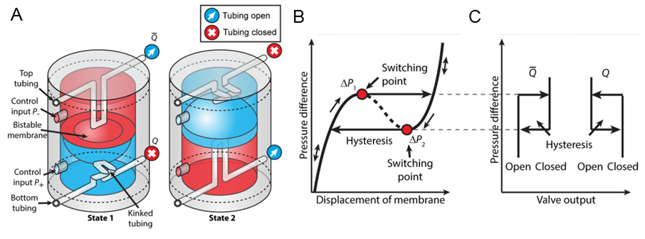
2. The soft, bistable valve The soft valve [8] consists of a hollow elastomeric cylinder (Figure 1A). A hemispherical membrane splits the cylinder into two chambers. The pressure difference between the two chambers deforms the membrane upwards or downwards (Figure 1A). The membrane exhibits a snap-through instability which causes a fast snapping motion when the membrane transitions through the center of the valve (at the switching points in Figure 1B). Elastomeric tubes lead through each chamber. Under axial compression the tubes exhibit a kink-instability that blocks air flow. When the membrane bends downward, it kinks the tube through the bottom chamber and allows air to flow through the top tube (Figure 1A,C). When it bends upwards, the opposite is true. Air flows through the bottom tube but cannot flow through the top tube. When the two instabilities are coordinated such that the tubes kink or open during the snapping motion of the membrane, the output of the valve has only two states, in which one of the tubes is open and the other tube is closed (Figure 1C, Video 1). Because of the hysteresis of the snap-through instability, the transition between the two states is also hysteretic (Figure 1B, C).
Figure 1: The soft, bistable valve. (A) The structure of the valve. (B) The pressure volume curve exhibits a snap-through instability. (C) The output of the tubes as function of the pressure difference across the membrane. Figure adapted from [8].
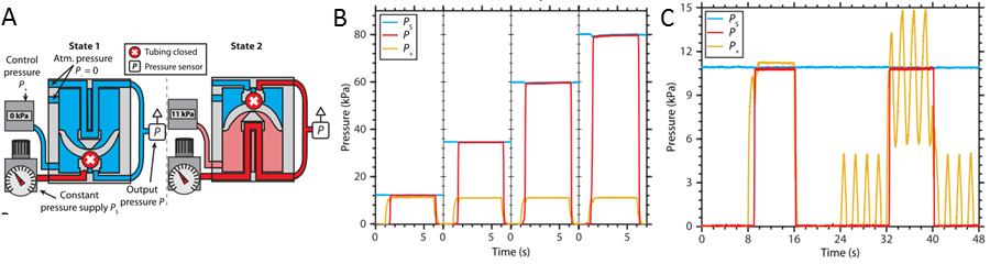
3. A soft switch Figure 2A shows a configuration in which the soft valve acts as a switch between two different pressures [8]. The bottom tube is connected to an air source of constant pressure, and the top tube is connected to atmosphere. After passing through the valve, both tubes are connected to a single output. The top chamber is connected to atmosphere. The state of the valve is controlled by the pressure in the bottom chamber. When this pressure exceeds the snap-forward pressure of the membrane, it snaps upwards and connects the output of the valve to the source of constant pressure (Figure 2A,B). When the pressure in the bottom chamber decreases below the snap-back pressure, the membrane snaps back and the output of the valve connects to atmosphere (Figure2A,B). The pressures at which the valve switches can be controlled by designing the material and geometry of the valve [8]. Because the membrane is large compared to the tubes it can even control pressures that are larger than the snap-forward pressure of the membrane (Figure 2B). This function is difficult to achieve with microfluidic valves. Because the output of the switch is binary and hysteresic, the switch can also filter noise in the control signal as long as the noise is small enough not to trigger the instability (Figure 2C). This function is comparable to that of a Schmitt-trigger in digital signal processing.
Figure 2: The soft valve as a switch. (A) Structure of the switch. (B) The valve acting as a switch. When no pressure is applied to the bottom chamber, the output is connected to atmosphere. When a control pressure (P+) larger than the snap-forward pressure of the membrane is applied to the bottom chamber, the output (P) switches to the air supply supply (Ps). (C) The valve can filter noise from the control signal. Figure adapted from [8].
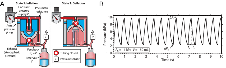
4. A soft oscillator In a feedback-circuit in which the output of the soft valve is connected to the bottom chamber, it can excite pressure oscillations in closed volumes (e.g., a soft robot) using air from a source of constant pressure (Figure 3A) [8]. The top tube is connected to an air source of high pressure, and the bottom tube to atmosphere. When the output pressure of the valve is below the snap-forward pressure of the membrane, air flows from the pressure source to the volume increasing its pressure. When the output pressure reaches the snap-forward pressure of the membrane, the membrane snaps and connects the closed volume to atmosphere. The volume vents until the output pressure decreases below the snap-back pressure and the membrane snaps back into the original position. This process leads to periodic pressure oscillations between the critical pressures for snapping(Figure 3B, Video 2) that may be used to control periodic motion in a soft robot. The speed of the oscillations is influenced by the supply pressure, flow-resistance of the tubing and the size of the closed volume to which the oscillator is connected [8]. Because the oscillator is soft, it continues to function after being crushed by a hard object (Video 3).
Figure 3: The soft valve as an oscillator. (A) Structure of the oscillator. The output is connected to the bottom chamber to create a fluidic feedback circuit, which excites pressure oscillations. (B) Example of pressure oscillations controlled by the valve. Figure adapted from [8].
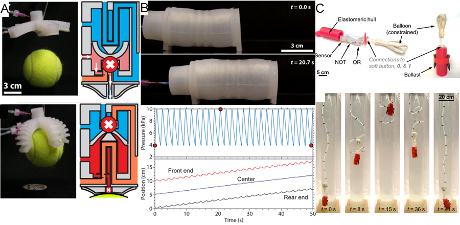
5. Simple autonomous functions enabled by the soft valve Figure 4 shows three examples in which the soft valve enables autonomous control of soft robots. We integrated the valve into the center of a soft gripper so that the gripper automatically closed when it touched an object (Figure 4A)[8]. The bottom chamber was connected to an air source of constant pressure above the snap-forward pressure of the membrane (Figure 4A). Because of an opening in the “palm” of the gripper, through which air could went, the pressure in the bottom chamber did not reach the snap-forward pressure. When an object touched palm of the hand and closed the opening, the pressure in the bottom chamber increased, the membrane snapped upwards, and the gripper closed to grab the object (Video 4). We also integrated the soft oscillator into a soft walker (Figure 4B) [8]. Using air from a source of constant pressure, the walker moved forward expanding and contracting periodically (Video 5). The soft valve may also be used as a controller, that reacts to changes of the environmental pressure [9]. Figure 4C shows a soft robot that oscillates between two levels of depth in a water tank. Initially, the robot is connected to atmospheric pressure, so that it sinks to a critical depth in which the hydrostatic pressure of the water is large enough to switch the valve. A balloon attached to the swimmer inflates and the robot raises up to a level at which the valve switches back. The balloon deflates and the swimmer sinks again (Video 6).
Figure 4. Autonomous soft robots. (A) A soft gripper that closes autonomously upon contact with an object. (B) A soft walker that advances using air from a source of constant pressure. (C) A soft robot that autonomously oscillates between to level of depth in a water tank. (A) and (B) adapted from [8]. (C) adapted from [9].
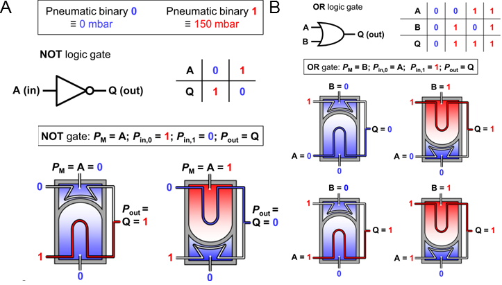
6. Soft logic gates Without modifications the soft valve can act as a logic gate and enable digital logic function [9]. In this case, a pressure above the snap-forward pressure is interpreted as "1", and a pressure below the snap-backward pressure is interpreted as "0". The function of the valve depends on how the chambers and the tubes are connected to external pressure sources. Figure 5A shows a configuration in which the valve acts as a "not" gate. The valve is designed such that the membrane bends upwards when no pressure is applied to the top chamber. The top tube and the bottom chamber are connected to atmosphere ("0"). The bottom tube is connected to an air source of constant pressure, which is interpreted as "1". When no pressure is applied to the top chamber (input "0"), the output of the valve is "1". When a pressure equivalent to "1" is applied to the top chamber, the output switches to "0" (i.e., the valve inverts the input signal). We have also demonstrated an "or" logic gate (Figure 5B), and an "and" logic gate (not shown here). This set of logic gates is functionally complete (i.e., any logic circuit can be build from these basic components) and can therefore serve as the basis for complex logic circuits.
Figure 5. Soft logic gates. (A) The valve is configured to act like a "not" gate. (B) The valve is configured to act like an "or" gate. The figure adapted from [9].
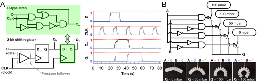
7. Digital, soft logic circuits As described above, the soft valve may be used as a building block for the digital control of soft robots [9]. We have implemented serial-in/parallel-out shift registers that allow the control of multiple actuators with a single control signal and a periodic signal (clock). Figure 6A shows a two-bit shit register that controls two parallel outputs. Every time the clock switches to state "1", the current state of the first output is transferred to the second output, and the currently applied input signal is transferred to the first output. Another circuit that we have implemented is a two-bit digital to analog converter (Figure 6B). The digital to analog converter transforms a two-bit digital input signal into four different levels of output pressure.
Figure 6. Digital logic circuits. (A) A two-bit serial in/parallel-out shift register. (B) A digital to analog converter. Figure adapted from [9]
8. Conclusions This blog-post discussed how instabilities of elastomers can control the air-flow in soft robots. The advantage of using instabilities for control is that they provide discrete states, which can be exploited for on-off control. Here, we combined two instabilities to design a soft valve: the snap-through instability of a membrane controls a kink-instability in tubing, which in turn regulates air-flow. There are many other instabilities in soft materials that may be used to fulfill these functions and that can be directly integrated into soft actuators.The advantage of the shown design is that it decouples the control (the pressure difference across the membrane) from the air flow (through the tubing), which simplifies the design of the entire control system. A single valve can be controlled manually but it also enables multiple different autonomous control functions. In addition, by combining multiple soft valves, complex digital logic functions can be implemented. This work represents a step towards autonomous, entirely soft robots that do not require any electronic or hard components.
References
[1] F. Ilievski, A.D. Mazzeo, R.F. Shepherd, X. Chen, G.M. Whitesides, Soft robotics for chemists, Angew. Chemie - Int. Ed. 50 (2011) 1890–1895.
[2] P. Polygerinos, N. Correll, S.A. Morin, B. Mosadegh, C.D. Onal, K. Petersen, M. Cianchetti, M.T. Tolley, R.F. Shepherd, Soft Robotics: Review of Fluid-Driven Intrinsically Soft Devices; Manufacturing, Sensing, Control, and Applications in Human-Robot Interaction, Adv. Eng. Mater. 19 (2017) 1–22.
[3] T.J. Wallin, J. Pikul, R.F. Shepherd, 3D printing of soft robotic systems, Nat. Rev. Mater. 3 (2018) 84–100.
[4] M.T. Tolley, R.F. Shepherd, B. Mosadegh, K.C. Galloway, M. Wehner, M. Karpelson, R.J. Wood, G.M. Whitesides, A Resilient, Untethered Soft Robot, Soft Robot. 1 (2014) 213–223.
[5] P.N. Duncan, S. Ahrar, E.E. Hui, Scaling of pneumatic digital logic circuits, Lab Chip. 15 (2015) 1360–1365.
[6] B. Mosadegh, C.H. Kuo, Y.C. Tung, Y.S. Torisawa, T. Bersano-Begey, H. Tavana, S. Takayama, Integrated elastomeric components for autonomous regulation of sequential and oscillatory flow switching in microfluidic devices, Nat. Phys. 6 (2010) 433–437.
[7] M. Wehner, R.L. Truby, D.J. Fitzgerald, B. Mosadegh, G.M. Whitesides, J.A. Lewis, R.J. Wood, An integrated design and fabrication strategy for entirely soft, autonomous robots, Nature. 536 (2016) 451–455.
[8] P. Rothemund, A. Ainla, L. Belding, D.J. Preston, S. Kurihara, Z. Suo, G.M. Whitesides, A soft, bistable valve for autonomous control of soft actuators, Sci. Robot. 3 (2018) eaar7986.
[9] D.J. Preston, P. Rothemund, H.J. Jiang, M.P. Nemitz, J. Rawson, Z. Suo, G.M. Whitesides, Digital logic for soft devices, Proc. Natl. Acad. Sci. 116 (2019) 201820672.
Miniaturization?
Hi Philipp,
That's great that you are trying to solve the long-standing issue of using rigid valves for controlling soft pneumatic actuators! The fact that you took it one step further to create high-flow-rate soft logic circuits is very cool. One of the biggest issues with pneumatics is that multi-channel control can quickly become very bulky. As it stands, these valves are very large. I know it wasn't the focus for this paper, but do you all have plans to decrease the size of the valves for miniaturized control? What are some of the limiting factors that you forsee for any such efforts?
Best,
Nicholas Kellaris
In reply to Miniaturization? by Nicholas Kellaris
Dear Nicholas,
Dear Nicholas,
I agree with you that the valves are currently relatively bulky. The physical principles behind the valve scale to smaller dimensions, but fabrication becomes difficult. It is no problem to scale down the bistable membrane, but we currently do not have a good way to scale down the tubing. Changes in design that allow the use of straight tubing will solve some of these issues. However, there is a general problem when scaling down valves for pneumatic robots: it reduces air-flow and, thus, limits the speed and the size of robots that can be controlled. Other researchers have shown that with microfluidics control can be implemented on a very small scale, but these fluidic circuits can only control very small robots.
Best
Philipp Rothemund
Untethered soft robots
Dear Philipp,
Thank you for sharing this simple but powerful design principle for soft robots. The progress in this field especially the pneumatic ones has been impressive in recent years. However, one drawback of such system is that they are usually tethered. Being untethered and pneumatic often requires some bulky system to generate power. I have also seen many modes of untethered actuation for soft robots such as magnetic, chemical, thermal, and light. Each of them has its own advantages and disadvantages. Could you share some thoughts on the direction of untethered soft robots? Such as promising candidates, design principles, or even simply how important this feature is in real applications. Many thanks.
Best regards,
Ruobing
In reply to Untethered soft robots by Ruobing Bai
Dear Ruobing,
Dear Ruobing,
I agree with you, that pneumatic soft robots (at least at the moment) require bulky control and air supply when they are untethered. Our work helps to reduce the number of rigid parts by integrating valves into the soft structure. Also if all pneumatic control and air supply could be integrated into the soft structures, pneumatic soft robots would likely require some electronic components when they are intended to navigate in unknown territory (e.g. optical sensors). Magnetic, chemical, and light operated actuators have been demonstrated untethered, but they require the actuator to be close to their energy source (for example an electromagnet).
I believe that the best candidates for untethered operation are electrically operated actuators (e.g., dielectric elastomer actuators, HASEL actuators, thermal actuators), because batteries and control can be miniaturized, even when high voltages are required.
Best
Philipp
Very excited research field
Dear Philipp,
The field of soft robots is really exciting and may unleash many new potentials. Thank you for sharing such a wonderful work. I still remember the early project you told me about soft rockets, can the rockets be powered by the pneumatic system you developed?
In your mind, what will be the future direction of this field? What are you planning to further explore this field? Is there anything in this field remain unexplored? Thank you!
Best wishes,
Jiawei
In reply to Very excited research field by Jiawei Yang
Dear Jiawei,
Dear Jiawei,
Thank you for your commet. The snap-through instability can be used to design a pressure release valve, that opens at a critical pressure. Thus, it could be used in a rocked-like robot, that propells by ejecting a stream of air, when it reaches a certain internal pressure.
In my opinion, one of the important next steps is to find new designs for the control system that allows miniaturization and simpler fabrication.
Best regards
Philipp
In reply to Dear Jiawei, by Philipp Rothemund
I am looking forward to your rockets
Dear Philipp,
Thank you for the brief answer. I am really looking forward to your rockets! Then what is the potential application of soft rockets?
Jiawei